|
The picture on the left shows an early
M4A1 lashed inside a ship, with the comb and a cable which runs from it
to the inside of the tank, via the hull MG (not mounted). Note the stencilling,
complete with a painted arrow, on the glacis:
|
|
Pete Harlem first published:
| "One guy wrote to say it was used to hold a rope that was tied to the transmission lock on vehicles being moved by rail. The rope, according to this theory, was pulled when the crew unloading the tank wanted to release the lock. Sounds good but why would it also be on non-Sherman vehicles then? And also why is it in different locations such as on the upper front left on some M-7s?" |
| "a second version made from sheet metal and curved rod stock that performs the same function so it appears there is more than one type although the first one I described is the most common encountered. It first appears on US tanks in Tunisia (intermediate hull M4A1s) and is on almost all Shermans from then on. Also it appears on M3s, M5s, M7s, M10s, M36s, and even a few M8 armored cars. The widespread use of it tends to shoot down all the theories we have seen on it." |
However, the option suggested to Pete Harlem of it being used as a shipping brake lock gained a foothold when Javier de Luelmo found the following photo:
(Please click on the photos (as applicable) to jump to large-scale copies)
|
The picture on the left shows an early
M4A1 lashed inside a ship, with the comb and a cable which runs from it
to the inside of the tank, via the hull MG (not mounted). Note the stencilling,
complete with a painted arrow, on the glacis:
|
John Eary
found a similar photo in R.P. Hunnicutt's Sherman. Page 326 shows
what seems to be the remnants of a comb with stencilling that looks like
"UNHOOK CABLE BEFORE TOWING" on a M4A3(76)W in Italy, August 1944.
Meanwhile, Joe
DeMarco recently came across the first printed documentation
seen to date regarding "the comb" or cable holding pawl.
He found it at the National Archives, in College Park, Maryland, USA:
|
Inspection Directive of the Chester Tank Depot -Ford Motor Company- Chester, Pa. Defining the scope and detailed coverage of inspection procedure required by the Army Ordnance Department of the Ford Motor Company in the receiving, storing, modifying, preparing and shipping of combat units and accessories. Feb.9,1943
All tanks and such units as are not boxed completely for export must have a brake control arrangement so that brake may be controlled from outside without breaking the seals on unit. A three-sixteenth or quarter inch wire rope cable with one end fastened to right-hand brake control then passed through right-hand hole of wooden plug in machine gun port, long enough to reach a pawl or series of saw tooth slots to hook cable then pass through left-hand hole in gun port plug and then fastened to the left-hand brake control lever. Cable must be so adjusted that brakes are locked and firmly set when cable has been pulled up and placed in second or third notch or slot of cable holding pawl or bracket, so that tank cannot be moved, towed or pushed without first releasing cable locking brakes. An instruction plate must be fastened to hull of unit just below or at end of cable holding pawl, reading as follows: N O T I C E
Cable outside
of tank to be painted to prevent rusting.
|
Joe continues: "The Chester directives include some marvelous photos, illustrating the use of the "pawl," the instructional stencil, the elaborate sealing of tanks for overseas shipment and the interior placement of desiccant."
(Please click on the photos (as applicable) to jump to large-scale copies)
 |
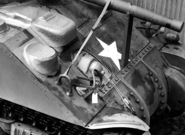
M4A4
prepared for shipping. The picture clearly shows all the sealed
hatches (except for the driver's hatch & vent!).
The detail shot on the left shows cables running through the hull machine-gun mount to the "pawl". |
 |
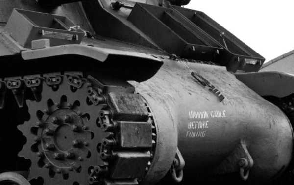
M7
105 mm HMC prepared for shipping.
The detail on the left shows the stencilling: "UNHOOK CABLE BEFORE TOWING" Note that the brake release cable runs into the interior under the gun mount. |
Only one question remained to be answered: how was the cable routed
in the interior so that the brake levers could be operated from outside?
Several enthusiasts had noted small pulleys behind the driver's seat,
and it was reasoned the cable could be routed through these to hold the
brake levers in their rear position with the cable under tension.
The proof of this theory came from David Herbert. In December 2000 he found some material mentioning a "Brake Control bracket" in the National Archives in Ottawa, Canada:
(Please click on the photos (as applicable) to jump to large-scale copies)
 |
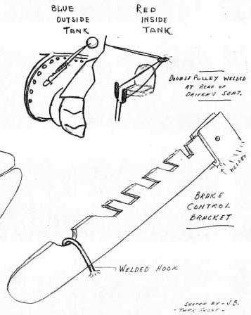
This rough sketch clearly
shows the hinged brake control bracket and how the cables
ran inside the tank from the hull machine-gun mount to the brake levers.
Noteworthy is that the full
sketch shows the brake control bracket fitted to a late type Ram
Cruiser tank (with integral hull machine-gun mount).
|
 |
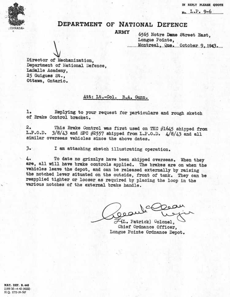
The above sketch was attached
to a Canadian DND letter dated October 9, 1943.
It mentions that the brake control bracket "was first used on TKC(1) #1645 shipped from the L.P.O.D.(2) 3/8/43 and SPC(3) [sic] #2557 shipped from L.P.O.D. 4/8/43 and all similar overseas vehicles since the above dates." (1) Tank,
Cruiser: Ram and Grizzly
|
Copyright © 1988-2001 H.L. Spoelstra / Sherman Register / All Rights Reserved