|
|
THE British Empire contains a large number of railway electrification schemes of considerable importance. The electrified railways of South Africa, which include the longest mainline electrification scheme in the British Empire overseas, and one of the longest in the world, are described on another page of this site. But India, Canada, Australia, and New Zealand have all sections of railway line electrified which deserve the close attention of readers of this work. They deserve attention because they are up-to-date examples of railway engineering technique of great interest. Further, since the man interested in railways may also be interested in the economic side of railway working, the reasons behind these electrifications are of wide application. These schemes in the British Empire have all been carried out by the British electrical manufacturing industry, and are in part responsible for its competitive strength and unrivalled technical experience. It is largely due to the success of railway electrification schemes in the British Empire that so much railway electrification in South America and in Europe has been undertaken by British manufacturers. We will deal first with India. The first railway electrification scheme in India was inaugurated in February, 1925, and consisted of the Harbour Branch of the Bombay suburban lines of the Great Indian Peninsula Railway. The engineers of the company had reported that the necessary intensification of the steam service along these railway lines could not possibly be considered as economically sound as conversion to electric traction. Suburban traffic was bound to grow along this line, and would eventually necessitate electrification. Before the conversion, the Harbour Branch consisted of a track from Kurla, some nine and a half miles from the main terminus in Bombay, up to a dead end at Reay Road, a few miles outside the city.
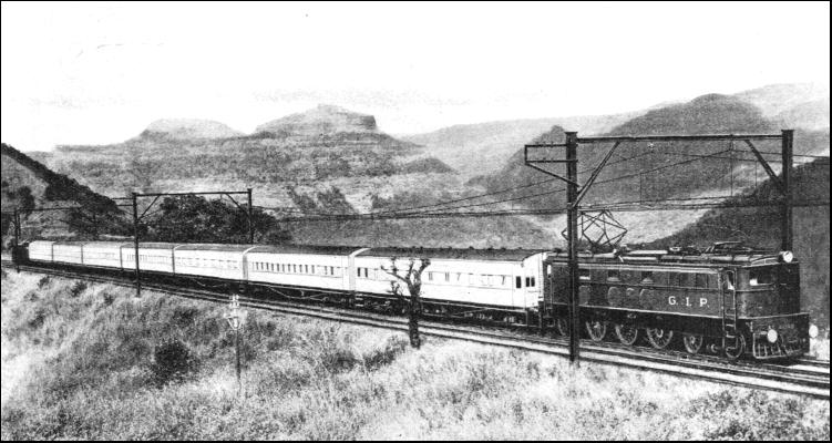
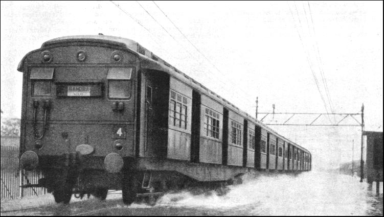
It was considered essential to carry this line right into the city, but because of certain restrictions affecting the intervening land, the only way in which the extension could be made was by carrying the track over a large goods yard. This bridging involved two considerable gradients, 1 in 42 on one side of the yard and 1 in 34 on the other side. These gradients practically ruled out economical steam operation, but were feasible with electric working. To have carried the Harbour Branch line into the terminus by any other route would have necessitated disproportionate expenditure. This consideration alone furnishes a good example of one outstanding advantage claimed for electrification, namely, its unique economy for operating on severe gradients. While work was proceeding on this Harbour line, the decision was taken to extend the suburban electrified section as far as Thana, twenty-two miles from Bombay. Subsequent extensions have prolonged the suburban electrification to Kalyan, thirty-four miles from the main terminus in Bombay. Suburban electrification on this comparatively large scale has certainly benefited the city of Bombay in reducing smoke pollution and making for better traffic conditions. Railway receipts have consistently increased as well. The track gauge on the G.I.P. is 5 ft. 6 in., and the rolling stock is large in proportion. A multiple-unit suburban train weighs about 418 tons, and has a seating capacity for 874 persons. Each motor coach is equipped with four 300 h.p. direct-current motors connected permanently in pairs in series for working on 1,500 volts. Current is collected from an overhead trolley wire by pantograph collectors, of which there are two on each motor coach, one being used at a time. The operation of the motors is controlled by an electrically-operated camshaft control equipment mounted in a compartment at one end of the coach. An interesting feature of the motors supplied for the first section of the electrification is that, although they are ventilated machines, they had to be designed so that the ventilating openings could be closed in the event of the track becoming badly flooded. At that time the line in question was subject to periodical flooding at several points during the monsoon season, and therefore the motors were fitted with special air valves so that they might operate satisfactorily even when there was water on the track to a depth of 2 ft. Before the electrification, traffic was often suspended because the water put out the fires of the steam locomotives, but electrical running has at no time been interrupted by flooding. The electrification of the G.I.P. main lines to Poona (S.E. of Bombay) and to Igatpuri (N.E. of Bombay) was a foregone conclusion once the suburban lines to Kalyan, which is the junction of the Poona and Igatpuri lines, was approved. The Igatpuri ascent includes about twenty-five miles of 1 in 100 gradient, followed by a short stretch of 1 in 60, and six miles of 1 in 37. The climb over the Bhore Ghat on the Poona line is shorter though more severe, the average gradient for fifteen miles being approximately 1 in 40, with a maximum of 1 in 37. The line then falls for some fourteen miles at an average of 1 in 200 towards Poona. The locomotives in use on this railway are the main engineering interest of the scheme. The passenger locomotives are each fitted with six 360 h.p. motors. In service, two are connected in series across a 1,500-volt D.C. supply to give a total capacity of 2,160 h.p. The locomotives are designed for high-speed service, and are capable of running at speeds up to seventy miles an hour. To ensure an ample margin of safety, they are made mechanically and electrically safe at speeds up to eighty-five miles an hour. A notable feature is the good flexibility that is obtained, the ratio between the maximum safe speed and the hourly rating speed being as high as 2.3 to 1.
The locomotive body extends the entire length of the frame, with a driving cab at either end connected by a corridor, and with the space between the cabs arranged in three parts. These are a switch and resistance chamber over the four-wheel bogie, a central chamber containing cam groups, and an auxiliary machine-room placed at the pony axle end of the locomotive. The driving motors are mounted in pairs, arranged end to end across the locomotives, and directly above the axle of the driving wheels to which they are geared. This arrangement not only keeps the motors above flood level, but also gives a relatively high centre of gravity, and a good longitudinal and transverse balance—all of which are essential qualities for an easy riding locomotive at high speed. The roof of each locomotive is fitted with isolating switches, lightning arresters, choke coils, and main equipment fuses, and with two pantographs for the collection of current from an overhead line. The freight locomotives are similar to those in use on the severe gradients of the Natal Railway in South Africa. They are fitted with regenerative braking, and arranged for working in multiple. The forty-eight freight locomotives first supplied to the G.I.P. Railway are articulated locomotives with the body supported at either end by pivots on two six-wheeled bogies carrying the driving motors. They are moderately slow-speed locomotives, but the high ratio of 2-1/2 to 1 between the maximum safe speed and the hourly rating speed indicates that a better idea of their capabilities is obtained by considering the tractive effort rather than the rated horse-power. The latter hardly conveys the full scope of the locomotives. The motors are capable of slipping the wheels easily under any conditions of rail. Consequently the maximum tractive effort is that obtained by the adhesion between wheel and rail, which may under certain conditions of rail reach as high as 33 per cent of the weight, or about 89,600 lb. tractive effort, the hourly rating tractive effort being 56,000 lb. The central body, containing the driver's cabs and control gear, is built upon one main longitudinal member along the centre, supplemented by the necessary side members. This member connects the two motor units by means of large spherical pivots at either end, which are supported in housings mounted in the bogie frames and through which the tractive effort is transmitted. Four spring-loaded side bearers are fitted under the ends of the main cross stays of the under-frame, bearing in sockets on the inner ends of the bogie frames, and arranged to give the necessary freedom between body and trucks in service. The inner ends of the bogies are further connected diagonally by a system of rods and bell-crank levers, arranged to minimize wear between the tyres and rail when negotiating curves. The centre body comprises a driver's cab at either end, interconnected by a corridor along one side, the remainder of the space being used to house the control gear and the auxiliary machinery. Two pantographs with the electrical roof equipment are mounted upon shield plates supported on insulators.
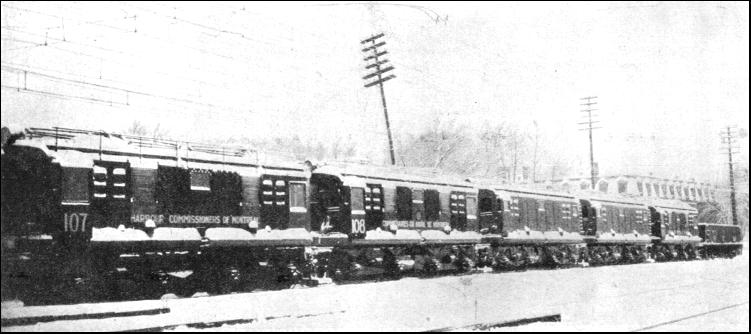
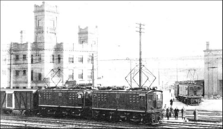
A further section of railway line electrified in India is the Madras suburban line of the South Indian Railway. At present this electrification (1,500 volts D.C. overhead) extends from Madras south-west to Tambaram, a distance of eighteen and a half miles. Although this is a suburban electrification, the multiple-unit services are supplemented by locomotives for hauling freight trains. Specially designed fool-proof electrical controls have been adopted on the locomotives and driving coaches. The electric motors are of the self-ventilating type, but, because of the exceptionally dusty conditions, ventilation is obtained from inside the coach through ducts and sliding joints. Among the most powerful four-axle freight locomotives in the world are those on the electrified lines of the Port of Montreal, which were converted to electric traction in 1925. Each locomotive is equipped with four single-reduction twin-geared motors, one driving each axle. Each motor is capable of giving 430 h.p. at the one-hour rating, and is of the forced ventilated type, receiving air through a sliding joint from fans mounted on and driven by the motor-generator set in the body of the locomotive. The motors provide a tractive effort at the tread of the wheels up to 70,000 lb. per locomotive. As a result the locomotives have been able to handle, as single units, the largest train that it has been necessary to bring into the docks. The heaviest train so far recorded that has been hauled, single-handed, by one of these locomotives weighed 5,240 tons. This was brought to the docks by two steam locomotives, and then taken over by one electric locomotive. The locomotives are arranged for working in multiple-unit if required. The control equipment is all-electric, embodying the well-known camshaft control principle developed by the English Electric Company, Ltd. To enable shunting operations to be carried out safely and easily, special arrangements had to be made to provide a driving position from which the operator could have a view in both directions. The locomotives are, therefore, constructed with the usual driving position at one end, but at the other end the driver's cab projects on either side so as to give a clear view up and down the track. This cab is fitted with duplicate controls, one at either side. The arrangement enables the operator to carry out all shunting operations from one end of the locomotive, the driving position at the other end being used only when it is the leading end on long hauls.
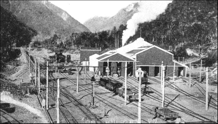
This freight yard electrification is interesting in that it shows the advantages of electrical operation in shunting, and, of course, where frequent starting and stopping of heavy trains have to be effected. The system of supply is 2,400 volts, direct current, to conform with an existing electrified section of the Canadian National Railways, through the Montreal Tunnel. The building of a railway across the Southern Alps which divide the South Island of New Zealand into two halves was one of the great feats of railway engineering in the southern hemisphere. Arthur's Pass is 3,000 ft. above sea-level, and Otira Tunnel, the longest in the British Empire, is 5 miles 445 yards long, with a gradient of 1 in 33. It is driven through solid rock. Electric working in this tunnel was insisted upon at the beginning, and a special power-station was constructed at Otira. Electric locomotives operating at 1,500 volts D.C. are used for haulage, power being supplied by two 1,200 kW 1,650 volts D.C. geared turbogenerators. Regenerative braking was not used, because the power-station supplies only the railway, and hence cannot use the current returned to it. Four brakes are fitted to the locomotives—Westinghouse automatic air, Westinghouse straight air, hand brakes, and rheostatic brakes. On the east side of Arthur's Pass the railway runs to Christchurch and then to the important port of Lyttelton. This latter section is electrified, largely because of the difficulties of working by steam traction a single-line tunnel near Lyttelton. The trains are hauled by locomotives at a speed of forty miles an hour with 600-tons trains. This speed has often been exceeded. Energy is obtained at 1,500 volts, 3-phase, 50-cycle current, and is converted to 1,500 volts D.C. in a sub-station containing rotary converters and automatic switching equipment. Although the State of Victoria is the smallest on the mainland of Australia, it ranks second in population, with a high concentration around the capital, Melbourne. Because of the high passenger traffic density on the Melbourne railways, electrification was decided upon in 1913, but it was interrupted by the war of 1914-18, and not completed until 1923. The electric tracks contain 350 track miles and over 150 route miles; the longest distance from Flinders Street Station in Melbourne being to Frankston, twenty-six and a quarter miles away. Partial electric services began on the Melbourne suburban lines in May, 1919. One advantage gained by electric working was an increase in the number of passengers carried from ninety-seven millions in 1918, the last year of all-steam working, to 156 millions in 1925. The annual increase after 1919 was more than twice as great as that experienced before the introduction of electric traction.
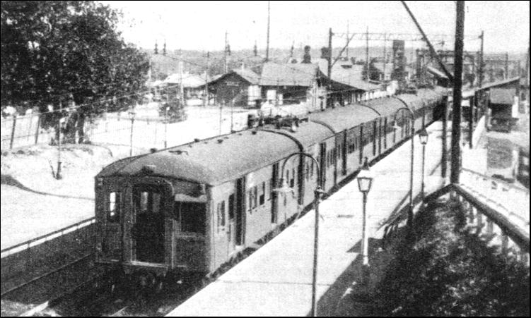
The electric services are operated by multiple-unit trains. A motor-coach with one trailer coach forms a train unit, three units being usually employed to form a train of six coaches. The motor coaches are each equipped with four 140-h.p. motors and one pantograph collector, taking current at 1,500 volts D.C. from an overhead line. A 78,000-kW power-station at Newport, four and a half miles from Melbourne, supplies 3.300 volt, 3-phase, 25-period current, which is converted by transformers to 20,000 volts for transmission by underground cables to the sub-stations of the inner area. Beyond this area overhead transmission is employed, the 20,000-volt conductors being suspended from extensions of the structures carrying the 1,500-volt D.C. contact wires over the railway tracks. A feature of both the Melbourne and Sydney electrified suburban sections is the electric express parcels service trains, which are widely used. In Melbourne, electric parcel trains running to fast schedules handle nearly all the parcel traffic between Melbourne and suburban stations. Sydney is the centre of a wide and boldly planned electrification scheme by which the bulk of all railway traffic to the north, south, east, and west is handled electrically to a distance of about twenty miles from the centre of the city. The continuous improvement which is being effected in the urban transport of Sydney is shown by the new Sydney Harbour Bridge with its four electrified tracks. There are now over 94 route miles electrified round Sydney on the 4 ft. 8-1/2 in. gauge. The first motor-coach trains used on the Sydney railways had an acceleration of 1.37 miles per second per second, which was four times that of the steam traction previously employed. The motor-coaches have a driving compartment at one end only, except for five that have one at either end. Nine of the trailer coaches are fitted with a driving compartment. All new motor-coaches have all-steel bodies with a motor bogie at one end and two side doors. The Sydney railway system provides a splendid example of intelligent planning and adaptation to the needs of one of the Empire's largest cities.
Many thanks for your help
|
   Share this page on Facebook - Share  [email protected] |

