|
|
THE earliest form of railway brake was an adaptation of the old horse-wagon brake : a block or blocks applied to the tyres of the wheels by means of a hand lever. In spite of the rapid progress in every other form of railway development, this primitive form of brake has survived to the present day and can be seen on most of the four-wheeled goods and coal wagons on any British railway. Because it was found deficient in power for locomotive purposes, the lever was replaced by a screw and nut, usually arranged in a vertical position at the front of the tender on the fireman's side of the locomotive. A cross handle, with one end bent up crank fashion, was attached to the top of the screw shaft, so that it could be operated quickly, and yet allow plenty of pressure to be obtained at the brake blocks. The nut was connected by a rod to the brake rigging, and the turning of the screw pulled up the nut and applied the brakes. This type of hand brake is still fitted to all locomotives, though it is not now used for service stops. It is useful in the rare instance of failure of the power brake, and can also be applied when the engine is left unattended. A similar arrangement was installed in the end carriages of each train in the old days (hence the term "brake van") and was operated by the guard on hearing a whistle signal from the engine. It was soon found that more powerful brakes were essential. The driver of an express train consisting of, say, a small "single-wheeler" locomotive (an engine with only one pair of driving wheels) and ten light four-wheeled carriages, travelling at about fifty miles an hour, had to shut off steam and start applying his brakes fully two miles before reaching a station at which he was booked to stop. The remedy for this was to apply the brakes by power. Steam was the only power available and small cylinders were installed under the engine and tender, the piston-rods being coupled to the pull-rods of the brake-gear by means of bell cranks. Steam was admitted to the cylinder by a brake valve similar to a three-way cock. With the handle in one position steam was allowed to flow to the cylinder from the boiler. With the handle in the other position, steam from the boiler was cut off, and the contents of the cylinder discharged into the atmosphere. The brakes were held normally in the "off " position by springs ; when steam was admitted to the cylinder, the piston was forced down, and the rod moved the long arm of the bell crank. The short arm of the bell crank operated the pull-rod, brake-beams and hangers, and applied the brakes, the pressure on the blocks being regulated by the amount of steam in the cylinder controlled in turn by the driver's valve. When the steam was released from the cylinder, the released springs pulled the brakes off. This was satisfactory for a while, but train weights and speeds kept increasing, and it became difficult to prevent engines from sliding with all wheels locked when the brakes were applied. The application of sand from the engine's sand pipes succeeded only in wearing flats on the wheel tyres.
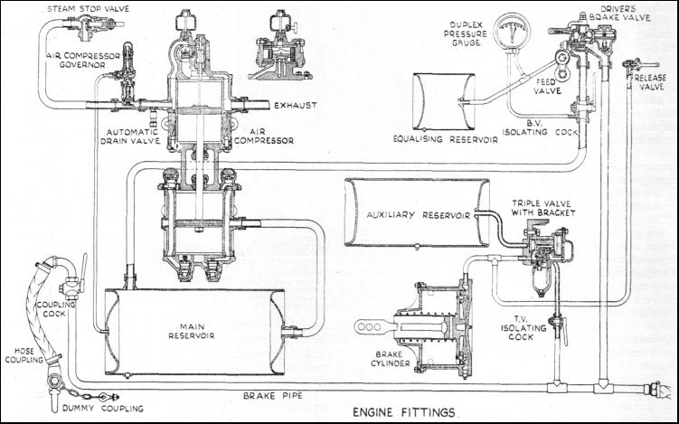
It was obvious that brake blocks should be applied to every wheel on the train. But it was difficult to find a means of doing this. Extension of the steam brake to the carriages was suggested, but was not practicable, as the steam would probably have condensed in the cold pipes before reaching the brake cylinder under each carriage. Inventors prepared schemes for continuous braking. Systems operated by chains, liquids, and compressed air were tried out on the different railways. After many experiments, a series of trials was arranged at Newark in 1875, in which nine engines and trains took part. The compressed-air brake invented by George Westinghouse in 1869, and further improved in 1872 to automatic action, made the best showing. It is this brake in its modern form that is in use to-day. George Westinghouse was quick to see that if steam would condense on entering cold pipes and cylinders, compressed air would not, and would operate the steam brake apparatus as well as steam itself. His first brake equipment consisted of the usual steam brake-gear on the locomotive and tender, and a cylinder under each carriage, the piston-rod of which worked the brake pull-rods. Each cylinder was connected to a continuous pipe running the full length of the train, connexion between the carriages being made by flexible hoses with universal coupling heads. Compressed air was supplied by a direct-acting pump (known to enginemen as a "donkey") and stored in a tank or reservoir in any convenient position under the engine. The driver's brake valve was of the "three-way cock" pattern, as used for steam brakes, and the action was very similar. To stop the train, the handle of the valve was moved forward and connected the main reservoir to the train pipe. Air flowed through the pipe into the brake cylinders, operated the pistons and applied the brakes. To release them, the handle was pulled back, and the train pipe opened to the atmosphere. Air rushed out, releasing the pressure on the brake pistons, and allowing the release spring to pull the blocks clear of the wheels. This brake was a great improvement on the old hand and steam brakes, but it had three drawbacks. It took a long time to apply and release, even on a train of moderate length ; it was "uneven" in action, as the engine and the carriages nearest to it had their brakes hard on before air had travelled to the last carriage ; if a train broke in two, and tore the hose couplings of the train pipe apart, all the air was let out and the brake was useless. To rectify these defects, George Westinghouse invented the "triple-valve," and applied it, plus an auxiliary air reservoir, to the brake cylinder of each carriage ; and in one ingenious move converted the brake into an automatic one, and speeded up its action.
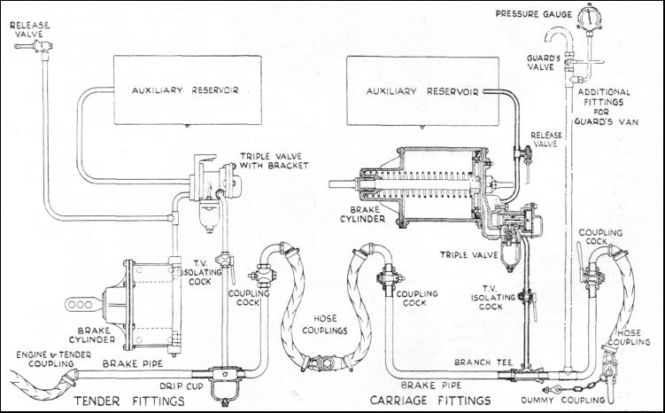
The triple-valve is a simple device performing three operations, hence its name. It applies the brakes, releases them, and charges the auxiliary reservoir. It consists of a chamber in which a piston works. The rod of the piston operates a slide-valve working over two ports, one of which communicates with the brake cylinder and the other with the atmosphere. The slide-valve side of the piston is in direct communication with the auxiliary reservoir ; the other side with the train pipe. To keep the brakes released, the train pipe must be charged with compressed air. This enters the triple-valve under the piston and forces it up to the limit of its stroke, moving the slide-valve to such a position that the cavity in it bridges the ports leading to brake cylinder and atmosphere. There is thus no pressure at all in the brake cylinder, and the release springs operate to keep the brake blocks clear of the wheels. When the triple-valve piston is at the end of its travel, it also uncovers a small groove, called the "feed groove," whereby air may pass to the auxiliary reservoir, and charge that to the same pressure as the train pipe. To apply the brake, the driver, by means of his valve, lets some of the air out of the train pipe, and so reduces the pressure on the underside of the piston in each triple-valve. The pressure in the auxiliary reservoir now being greater than that in the train pipe, the piston is forced down, closing the feed groove and bringing the slide-valve with it. The latter first shuts the port communicating with the atmosphere, and then opens the port leading to the brake cylinder, allowing air to flow from the auxiliary reservoir into the brake cylinder, and applying the brakes. A small additional valve, called a graduating valve, is also connected to the piston in such a way that it closes the brake cylinder port while the piston is stationary. This enables the driver to control the braking power by regulating the air pressure in the train pipe. When the driver wishes to release the brakes after application he admits air, by means of his control valve, to the train pipe from the main reservoir on the engine. This pushes up the triple-valve pistons, shuts off the air from the auxiliary reservoirs, and lets what is in the brake cylinders escape into the atmosphere by way of the cavity in the slide-valve, and the exhaust port in the triple-valve. At the same time the auxiliary reservoirs are recharged through the feed grooves. All the time the train is in service the pressure in the train pipe must be maintained to keep the brakes in "release" position ; and it will thus be seen that, should a train break in two, and the train pipe hose couplings be torn apart, the sudden release of air from the train pipe would operate all the triple-valves on the train, and the brakes would be applied automatically at full force.
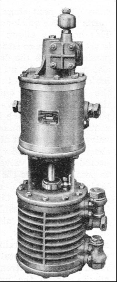
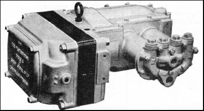
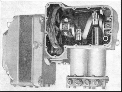
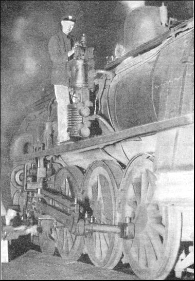
Another advantage is that the guard of the train has an emergency control, as a cock is provided in his van, by which he can release air from the train pipe, and stop the train in the event of emergency. In most trains the passengers' alarm signal chain is also connected to an air valve, so that any passenger who "pulls the communication cord" not only gives the alarm, but also begins the application of the brakes. Trains still increased in length and weight Once again it was found that the brake was becoming too slow in action, all the air for operating it having to pass through the driver's valve. The brake was thus applied with greater force at the front end of the train, to the discomfort of the passengers and the detriment of the couplings and draw-gear. The next stage in the improvements was the quick-acting triple-valve. This not only allows some of the air in the train pipe to escape direct without passing through the driver's valve, but also makes it do useful work in the brake cylinder, and helps to apply the brakes much quicker than with the ordinary triple valve. It has two pistons, one of which is arranged horizontally and is connected to a slide valve similar to that already described ; the other is arranged vertically and connected to a small valve which allows air to pass direct from the train pipe to the brake cylinder. In normal working, only the horizontal piston moves, and the action of the triple-valve is much the same as that already described ; but when a quick stop is required, and the air in the train pipe is suddenly released, the horizontal piston is brought rapidly to its extreme position and admits air to the upper side of the secondary or vertical piston. This is driven down and opens a valve which lets air flow direct from the train pipe into the brake cylinder, resulting in a sudden further drop in the train pipe pressure and causing the adjacent "triples" on the next coach to operate in a similar manner. On a test with a fifty-car train, it was found that the brakes could be fully applied with the quick-acting triples in one-sixth of the time taken with the ordinary triples. To release the brakes, the action is reversed, as previously described ; but to ensure that all the brakes are released together, the exhaust ports are fitted with nipples which are bored to a size determined by the size of the brake cylinder fitted to the carriage or car. There is yet another kind of triple valve which is the same in principle as the foregoing types, but has certain improvements that tend to produce simultaneous action of the whole of the brakes in the train, and is so arranged that the local reductions of pressure in the forward end of the train pipe produce a correspondingly quicker action of the triples at the rear end. Other improvements in the valves, ports and passageways tend to produce the smooth, swift action of the modern brake as used to-day. There are several varieties of steam-driven compressors, but the principle is the same in all, though some are single cylinder and some twin. The "singles" have a steam cylinder at the top, coupled to a single, two, or three-stage pump cylinder below it, the pistons of both cylinders being mounted on a rod common to both, and passing through glands in adjacent cylinder covers. The valve gear is ingenious. A slide valve distributes steam to either end of the steam cylinder in turn, but it cannot be operated by a direct connexion with the piston-rod ; otherwise when the valve covered both ports, the main piston would stop. It is moved by a spindle having a different-sized auxiliary piston on each end, steam to which is controlled by a small reversing valve operated by a tappet rod working inside the hollow main piston rod. As the steam is admitted between the pistons, it naturally exerts greatest force on the larger one, and moves it over together with the valve, letting steam pass in to one end of the main cylinder. When the main piston reaches the end of its stroke, the tappet rod operates the reversing valve and admits steam to the other side of the larger piston on the slide-valve spindle, "balancing" it. As all the pressure now comes on the smaller piston on the other end of the slide-valve spindle, it moves over towards that side and shifts the slide-valve to the other extreme, admitting steam to the opposite end of the main cylinder, completing the stroke.
The pump in the single-stage compressor is merely a double-acting cylinder with an inlet and exhaust valve at either end, the passages leading from the exhaust or "discharge" valves being connected to the main reservoir on the engine. The two-stage compressor has two pump cylinders of varying size. Air is first compressed to moderate pressure in the larger one, and from there it goes to the smaller one directly beneath it, where it is finally compressed to full pressure and delivered to the main reservoir For very high pressures the air-pump piston is made hollow, like an automobile engine's piston, and not only works in a cylinder but also has a stationary piston inside it, over which it slides. Air is first compressed under the piston, then between its skirt (which is fitted with rings) and the upper end of the cylinder, and finally between the underside of the skirt and the discharge valves. Many compressors, especially those used in Canada and U.S.A., have two unequal-sized steam cylinders and two pump cylinders, and work "compound" which means that steam is first used in the smaller steam cylinder, exhausting from that into the larger one, where it does more work before finally exhausting into the atmosphere. Similarly, air is compressed to moderate pressure in the larger air cylinder, and from there it goes to the smaller one, where it is increased to full pressure and discharged into the main reservoir. These reservoirs, also the auxiliary reservoirs under the coaches, are merely cylindrical steel tanks with either riveted or welded seams, built to carry a working pressure of 90 lb. per sq. in. The actual brake-gear is well known to everyone who is familiar with train equipment. Everybody is acquainted with the small cast-iron blocks which hang close to the locomotive and carriage wheels. These blocks are suspended from hangers and are worked by the cross-beams and pull-rods which connect them to the piston rods of the brake cylinders situated under the coaches, securely bolted to the under-frames. These brake cylinders are like many other cylinders, containing the usual piston and rod, and also a spring round the piston-rod, in some types, which returns the pistons to the end of the cylinder after the brakes have been applied and released.
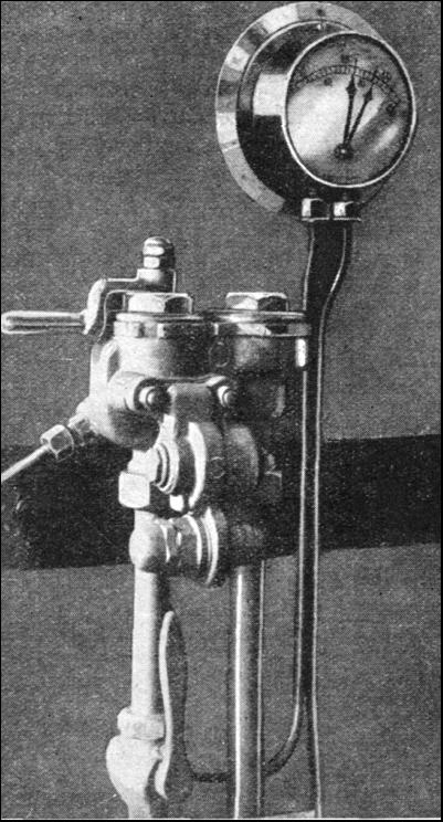
Among the interesting "gadgets" used in the working of the brakes are the compressor governor and the driver's brake valve. The former is an ingenious device mounted on the steam-pipe close to the compressor and contains a steam valve connected to a piston worked by air pressure. When the air in the reservoir reaches a predetermined pressure it acts on the piston, which shuts off the steam valve and stops the pump. When the air pressure falls, a spring in the head of the governor-casing opens the valve again and restarts the pump, thus saving the engineman the trouble of attending to the pump, and regulating the air pressure. The driver's valve consists of a slotted and holed disk valve working over a port-face, and is provided with a handle which has five positions ; first, to release brakes and charge the train pipe ; second, running position—brakes released and held ; third lap position—all ports closed ; fourth, service application ; fifth, emergency application. Passengers on some of the suburban lines are under the impression that the driver uses the fifth position every time he pulls up. When a. train has two engines, the leading driver controls the brakes, the brake valve on the second engine being cut out of action by a cock on the air pipe, called an isolating cock. Isolating cocks are also used on the coaches to cut out defective triple valves and brake cylinders, so that the train may be worked with the rest of the apparatus in action. Duplex pressure gauges are fitted on the engine, indicating to the driver the pressure in main reservoir and train pipe : and single needle gauges, showing train pipe pressure, are provided in the guards' brake vans. The Westinghouse brake, as fitted to modern electric trains, has much in common with that on steam trains, the principal difference being that the compressor is operated by an electric motor, and usually has two pump cylinders. The motor is geared to a shaft like an automobile engine's crankshaft, and the connecting rods and pistons bear a similar resemblance, ordinary types of suction and discharge valves being used. The simplest type of governor is similar to a pressure gauge, the needle making a contact at its low-pressure limit which switches on the motor. and another at its high pressure limit which cuts it out and stops the pump. The compressor is the cause of the intermittent thudding which is constantly heard under the Southern Electric, District, Metropolitan, and other electrically-operated lines.
Quick-acting brake gear is used, and on some of the "tube" railways the brake blocks are lined with Ferodo or similar fabric lining, to give a better co-efficient of friction than plain cast iron, and to minimize the wear on both brake-blocks and wheel tyres. Wear is a serious item when trains make hundreds of stops a day, as on the London Underground. A far more rapid-acting brake can be applied to electric rolling-stock than is possible on any steam train, as electric current travels faster than compressed air ; and on modern electric trains, where instant application and release are needed, the brake application and release valves under the coaches are operated by electro-magnets fed with current from a small controller interconnected with the driver's brake valve. The brakes on a train of any length can therefore be applied or released practically instantaneously ; and in the rare event of the failure of the electrical part of the apparatus, they can be operated purely by air in the ordinary manner, though not so quickly. Most electric trains have two or more motor coaches, all of which are furnished with driver's brake valves ; but those not in use are always cut out by means of an isolating cock and switch. In common with every other invention of great utility, the Westinghouse brake stimulated the work of other inventors, who devised various alterations and more or less useful variations ; and the principle of the complete apparatus has been made the basis of other forms of air brakes. These include the "New York" air brake, used in U.S.A., one form of which employs a direct-acting duplex donkey pump "upside down," the steam cylinders being at the bottom, and the air-compressing cylinders at the top ; the "Knorr" airbrake widely used in Germany ; and various others. The latest form used in Russia has an extra train pipe connected to the auxiliary brake reservoirs under the cars, with special valves arranged so that as the train pipe pressure decreases, and the triple valves operate and apply the brakes, the air pressure in the auxiliary reservoirs (and consequently the braking power) can be increased, thus giving a more powerful application for the same air consumption. In the event of a burst hose, or a break-away, the brakes work normally. In U.S.A. and other countries where grades fifteen miles or more in length have to be negotiated with heavy trains, retaining valves are fitted, which enable the auxiliary reservoirs to be recharged without releasing the brakes. In contrast to the Westinghouse brake, using air under pressure, another type is the automatic vacuum brake, which is used on steam trains. With this brake air is exhausted from one side of a piston in a cylinder, so that the air pressure of the other applies brake-shoes to the train wheels.
Many thanks for your help
|
   Share this page on Facebook - Share  [email protected] |

