|
|
THE need for marshalling yards arises from the obvious fact that goods and merchandise from any large industrial area has to be distributed throughout the country ; and marshalling yards are the centres where train loads of these goods are sorted out prior to their being dispatched. Thus from a particular colliery a train load of coal may set out consisting of a number of wagons destined for a number of different districts. This train will be passed through a marshalling yard, where it is split up and sorted out, its individual wagons being run into different sidings. The next train in is sorted in the same manner, so that wagons destined for the same district are run into the same siding from the two trains. Each siding, in fact, is allocated to a particular district, and trains for these districts are gradually made up as more trains are run into the yard. Speed of working is essential—especially when perishable goods such as fish and fruit are being handled. The shortest possible time must elapse between the arrival of a wagon at a yard and its departure. Marshalling yards consist of two main parts, the reception roads, into which trains to be sorted are run on arrival, and the classification or sorting sidings into which each train is sorted out. In hump yards, such as are situated on the L.N.E.R. at Whitemoor, these two main sections are connected by a "hump."
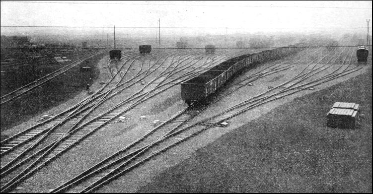
Wagons are pushed over this hump and are allowed to run down the other side into the sorting sidings. The height and gradients of the hump vary in different yards to suit different conditions, but the main principle is that it must be designed to give sufficient momentum to carry wagons into the sorting sidings for which they are intended. With this layout—reception roads, hump, and classification sidings—long trains can be pushed over the hump at a steady speed and are split up much more speedily than is possible with ordinary flat shunting, where the engine has to be continually stopped and reversed as wagons are run off the end of the train. In connexion with this it is interesting to note that at Whitemoor, where there are two yards, trains of seventy wagons or more are split up in the very short time of seven minutes, and about 1,500 wagons can be dealt with in each yard in one shift of eight hours. As the yards work twenty-four hours a day for six days a week, it will be realized how great a number of wagons can be passed through them. In a flat shunting yard the seventy wagons referred to would take about one hour to split up. There are two marshalling yards at Whitemoor, one for dealing with "up" traffic and one for "down" traffic. The. two yards are arranged side by side, with the main line from Ely to Spalding running between them. Whitemoor itself is situated just outside March Junction Station. It lies conveniently between the Yorkshire and Derbyshire coalfields, the Peterborough brick fields, the fish districts of Grimsby, Hull and Goole, the fruit districts, and London and the South of England. Besides these commodities, the yards also have to handle a large amount of sugar beet during the season.
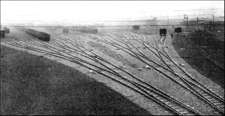
Both the yards are provided with ten reception roads, providing ample room for trains to stand while awaiting their turn for classification. The reception roads in each instance converge on to one track running down the hump into the classification sidings, of which there are forty in the up yard and forty-two in the down, each with a special brake wagon siding and crippled wagon repair roads. The two yards are connected by a transfer road which enables any necessary exchange of traffic between them. Their total capacity is 10,500 wagons. The sorting sidings are arranged in "balloon" or "fan" formation. That is to say, instead of all the sidings being taken off one long lead, as is done in the "ladder" layout, the main lead first splits into two at the "king points." These two are then split into four, the four into eight, and so on, the result being to get a number of groups of tracks with approximately the same number of sidings in each group. This has the effect of reducing the distance between the first and last sets of points, and tending to make all the sidings of equal length. Should any mishap such as a derailment occur, the yard is not blocked as it would be with "ladder" layout ; all of which provides quicker sorting. Some idea of the large amount of work entailed in laying down these yards may be gathered from the fact that the up yard alone entailed the excavation of some 250,000 cubic yards of material and the laying of about thirty miles of track.
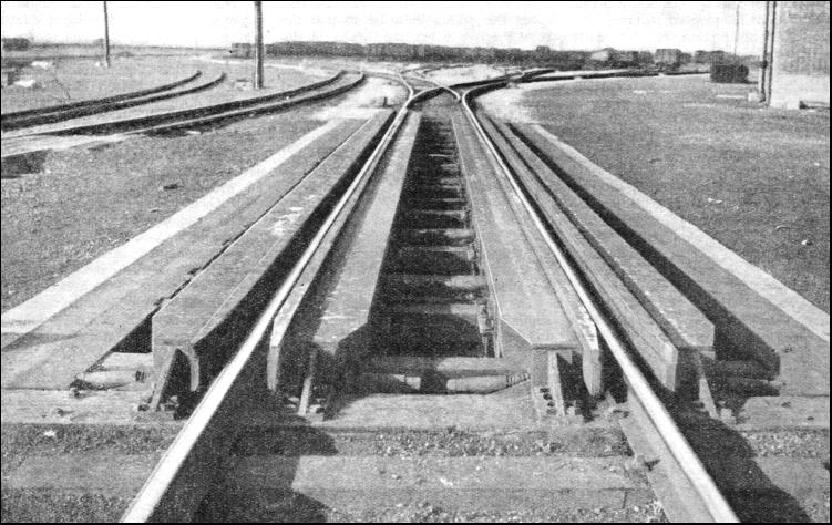
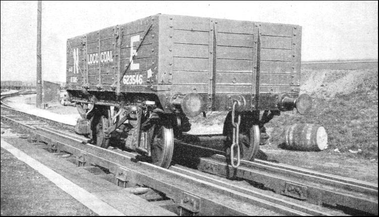
Both yards are equipped with retarders, or rail brakes, the up yard having four hydraulic brakes and the down yard two eddy current brakes. The retarders are placed at the foot of the hump on the first four—or in the down yard the first two—leads after the king points. Their purpose is to slow down the railway trucks which are travelling at too high a speed and to keep a suitable spacing between successive wagons. It is necessary to brake the wagons as they run off the hump, to prevent them from colliding with the vehicles already in the sidings, and so causing damage both to the wagons and their loads. The purpose of these rail-brakes is to do away with the braking by hand required in an ordinary hump yard, where a large staff is needed. This hand-braking always involves risk. Further, the steepening of the hump gradients at Whitemoor, to accelerate the sorting, causes the wagons to run down at greater speed, and makes a powerful system, of braking the more essential. The intensity of the braking force, with these rail-brakes, can be adjusted according to whether the siding into which the wagon is about to run is full or empty ; in the latter instance a longer run is needed, and the brakes will be applied with less severity.
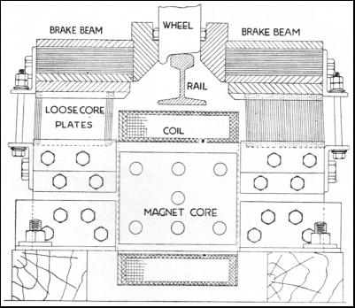
The brakes consist of four longitudinal brake beams, one on either side of both running rails. Two of these beams are fixed and the others are pivoted, as shown in the diagram of the hydraulic brake below. These beams are carried on a table or platform which, in turn, is mounted on the pistons of a number of hydraulic cylinders. Thus when water at pressure is admitted to the cylinders the whole table moves upwards, so that the " feet " of the .brake beams engage with the flanges of the wheels and results in the squeezing of the wheels between the brake beams. If the pressure in the cylinders is increased sufficiently the wagon will be lifted off the running rails and will ride on the feet of the pivoted beams. In the construction of the eddy current brake, as used in the down yard, there are four brake beams, two for each rail. These beams form the north and south poles of a large electromagnet and are mounted on packets of loose plates which in turn rest on massive iron "cores." These cores are spaced about 7 ft. apart throughout the length of the brake, and round each is a coil which is supplied with direct current. Thus when the coils are electrically energized the whole brake becomes a large electro-magnet, with the brake beams as its poles. As these poles arc mounted on loose plates, they pull inwards on to the wagon wheels. As the wagon passes through the brake the wheels rotate in a strong magnetic flux and eddy currents are set up in the wheel tyres, thus retarding the wagon. This effect can be reproduced simply by rotating a disk of any electrically conductive material between the poles of a horse-shoe magnet. While a certain amount of friction must necessarily be present owing to the fact that the beams are actually in contact with the wheel tyres, the main braking effect is obtained by eddy currents, and it is this fact that distinguishes the action of this brake from that of the hydraulic brake, which relies entirely upon friction. Springs are provided at intervals along the brakes in order to pull the beams apart when the brake is de-energized.
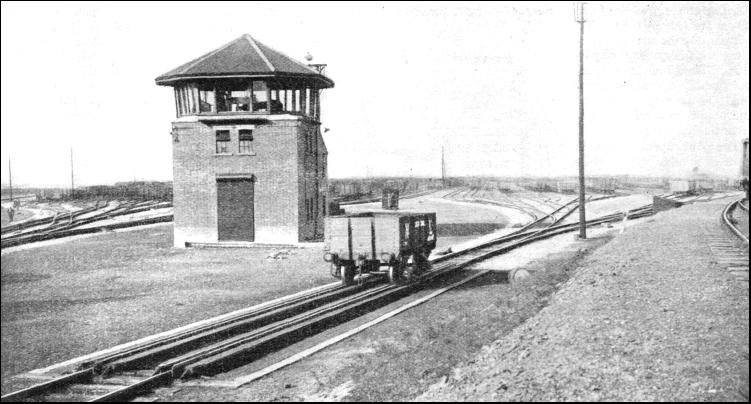
All the points throughout the yards are power-operated, the point machines having electric motors operated on 110 volts D.C. They are especially designed for hump-yard working, and are built for high-speed point shifting ; their time of operation is 0.6 sec. Control towers, from which the railway staff carry out the sorting and marshalling operations, are placed dose to the "king points" from which the tracks spread out. The control towers of each yard are similar and are built in three stories. In the bottom story is housed the power plant for the retarders—hydraulic pumps and accumulator for the hydraulic brakes and mercury-arc rectifiers for the eddy current brakes—and the batteries for point operation and track circuits. This power plant in the up yard consists of two 20 h.p. motors— one as a stand-by—each driving a three-throw pump. There is also a small rotary converter for trickle-charging the batteries. In the down yard the power equipment consists of two glass-bulb mercury-arc rectifiers and their transformers. The electric supply comes in from the railway company's power house at 3,300 volts A.C., from which it is transformed down to a suitable voltage for the rectifiers which convert it to D.C. for the actual operation of the brakes. In this yard the batteries are trickle-charged through a metal rectifier.
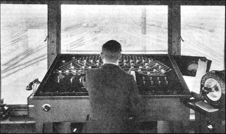
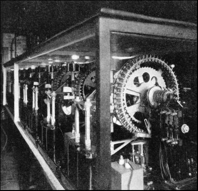
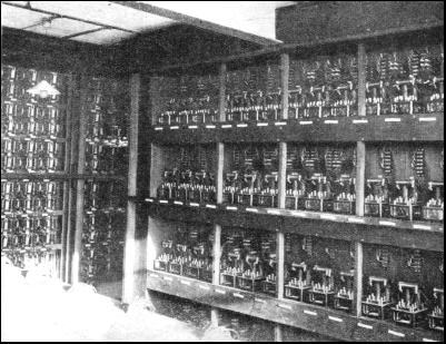
On the second story are housed the track relays, and the storage drums for automatic point setting. On this floor is also situated the operators' mess-room in which the men take their meals. This room is fitted with lockers, and an electric cooking stove is provided for the operators' use. The top floor of the control tower may be said to constitute the "brains" of the yard. It is from here that the traffic through the yard is controlled. Its sides are of glass, mounted at a slight angle to avoid glare, and from it a complete view can be obtained of the entire yard. The men who control the points and the brakes work in this room. In the up yard three men are employed, one to operate the switches and one for each pair of brakes, and in the down yard there are only two. When a train arrives in the reception roads, a shunter goes along it splitting it up into "cuts." A cut consists of one or more wagons adjacent to each other which are destined to be run into the same track in the sorting sidings, and instead of uncoupling them and running them down separately, they are left coupled up to one another and are run down as one unit or cut. As the shunter goes down his train splitting it up, he makes out what is called a "cut card." This is a sheet of paper on which are put the details of all the cuts in the order in which they will eventually be pushed over the hump. The cut card shows not only the number of wagons in each cut, and the number of the siding into which each is to be run, but also any special remarks necessary. One of these cut cards is clipped to the board on the right of the ccntrol panel, while the one on which the operation is actually working is clipped on to the panel in front of him. Several carbon copies are made of the cut card ; one copy is kept in the head shunter's office at the top of the hump, and the others are sent by means of a pneumatic tube to the control tower for the use of the operators. Thus both the point and brake operators know what is coming over the hump and can deal with it accordingly.
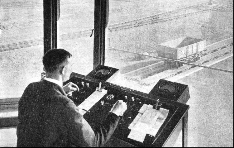
The point operator sits in front of a table with a sloping metal top panel which is laid out diagrammatically to represent the arrangement of the yard. On this top panel the tracks are also represented, either with aluminium paint or metal strips. Thumb switches for controlling the point machines are mounted in appropriate positions, so that when they are thrown they complete the painted, or raised metal, representation of the track corresponding to the route actually set. Each thumb switch has three lamps associated with it, one for normal and one for reverse indication of the points, and one, situated between these two, which lights up when the track over the points concerned is occupied. Thus by means of the first two lamps the operator can tell at a glance whether the points follow the throwing of the thumb switch, and by the third lamp he knows as soon as a wagon enters and clears any particular set of points. At the extreme end of each of the diagrammatic tracks is a red lamp which lights up when the siding concerned is full, to give warning to the operator that any further wagons sent into that siding will obstruct the entry to the siding adjacent to it. Also mounted on the point control panel are thumb switches for the operation .of the signals throughout the yard. The first seven pairs of points in the yard—the king points—and the next three on either side of it are arranged to be automatically operated. These seven switches split the yard up into eight groups. These groups, for the sake of convenience, are lettered A to H inclusive; in the photograph of the control cabin is seen an instrument on which a plunger with a pointer attached is capable of being rotated over a scale on which are engraved the letters A to H corresponding to the eight groups of tracks previously mentioned. The thumb switches controlling these seven pairs of points have three operating positions. Besides the usual normal and reverse positions there is a centre position which is used for automatic working. With the seven thumb switches in their centre position, the operator turns the pointer towards the group required and presses the plunger. This has the effect of setting up a route from the king points to the group required on the storage drums.
In front of him the operator has a "cut card" on which is a list of all the wagons constituting the train about to be "humped" and the order in which they will come down the hump. So that for each cut on his card the operator sets up the correct route of his storage drums. He need now no longer bother about these points, as each cut, on passing over them, automatically sets them in the correct position for the following cut. The remaining points have, of course, to be thrown by the operator by means of the thumb switches in the usual manner. A microphone and loud speaker are placed on the cabin wall above the operator in order that he may talk with the head shunter at the top of the hump. The control panel for the two eddy current brakes in the down yard is operated by a brakesman by means of handles, one for each brake, which he can turn from the "off " position to any one of three energized positions. Position 3 is the full energization position, and 1 and 2 intermediate positions. This operator also has a cut card in front of him and he ticks off each cut as it passes through his brakes. The control gear of the hydraulic brakes in the up yard is different from that of those in the down yard, and here the operator has a vertical lever which he pulls towards him. The farther he pulls his lever over the greater is the braking force obtained.
Adjacent to the two marshalling yards, the L.N.E.R. has a large and up-to-date locomotive depot capable of housing up to 200 locomotives and complete with modern coaling plant, washing sheds and sand-drying plant. The new power house, which was built about the same time as the down yard, supplies power for the retarders in the down yard, the pumps for the hydraulic brakes, the coaling plant and also all the lighting of the yards. This latter item is considerable, as both yards are efficiently flood-lit for night working. Without an efficient lighting system it would be impossible to work the yards continuously during the twenty-four hours. The hump yards at Whitemoor are situated one on the "up," the other on the "down" side of the main line. They provide yet another example of railway work "behind-the-scenes," dealing expeditiously with an enormous volume of goods traffic destined for distribution throughout the British Isles.
Many thanks for your help
|
   Share this page on Facebook - Share  [email protected] |

