Civil War Field Fortifications
Lines with
Intervals
Nineteenth century manuals describe at least three distinct
systems for arranging field works within lines with intervals. D. H. Mahan
offered a system composed of three distinct lines of works in his Complete
Treatise on Field Fortifications. Mahan's first line was composed of
lunettes or square redoubts with salient angles 250 yards apart. Each
lunette, which Mahan preferred over redoubts because they were open at the
gorge and their interiors were subject to fire from the second line, was
to be large enough to conveniently shelter a garrison of 300 to 400 men and
a field battery and have 90 degree salient angles with faces about
60 yards and flanks 40 yards long. Each lunette was to be positioned to project
columns of fire well across the fronts of the salient angles of collateral
lunettes. The gorge of each lunette was to be obstructed with abatis or
palisading to prevent the enemy from gaining easy access to the
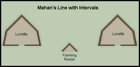 rear of the
work. The size of Mahan's prescribed garrisons for the works of the first
line suggests that each lunette was to have its own reserve and be able to
defend itself independent of the other works in the line. The second line
was composed of redans with faces about 40 yards long which were positioned
to cover the intervals between works of the first line with the faces directed
to project their columns of fire across the faces of the lunettes of the
first line. Second line redans were to include an armament of artillery
to increase the strength of supporting fire for the first line. In positions
where cavalry could be used to advantage a third line consisting of large
epaulments could be constructed 200 yards in rear of the salients of the
first line to protect the cavalry from enemy fire while they awaited orders
to advance with the reserve to counter the enemy. These works were only intended
for the protection of cavalry and were not prepared for defense with banquettes
or artillery platforms.
rear of the
work. The size of Mahan's prescribed garrisons for the works of the first
line suggests that each lunette was to have its own reserve and be able to
defend itself independent of the other works in the line. The second line
was composed of redans with faces about 40 yards long which were positioned
to cover the intervals between works of the first line with the faces directed
to project their columns of fire across the faces of the lunettes of the
first line. Second line redans were to include an armament of artillery
to increase the strength of supporting fire for the first line. In positions
where cavalry could be used to advantage a third line consisting of large
epaulments could be constructed 200 yards in rear of the salients of the
first line to protect the cavalry from enemy fire while they awaited orders
to advance with the reserve to counter the enemy. These works were only intended
for the protection of cavalry and were not prepared for defense with banquettes
or artillery platforms.
The two most notable features of Mahan's line were the
strength of its artillery armament and the inability of guns mounted in the
retired redans to reach the interiors of the advanced lunettes with their
fire. Given field batteries of six guns in each advanced lunette arranged
with three guns firing from each face and at least two guns on each face
of the retired redans, the space between collateral lunettes, 250 yards wide,
would be covered by ten field guns and howitzers. This concentration of artillery
within a limit area indicates that the lunettes and redans were primarily
intended as artillery positions which could be protected from close assault
by their infantry garrisons. Not only would the artillery provide the
strongest part of the defensive fire delivered from the works, their fire
could also support troops advancing through the intervals to attack the enemy.
Mahan's system arranged the retired redan in a manner that prevented
their artillery armament from gaining a direct fire into the interior spaces
of the advanced lunettes. The redans were placed too close to the line of
the gorges of the advanced lunettes and their faces did not extend far enough
to the rear to overlap the flanks of the lunettes. An enemy force, having
capture a lunette, would be protected from the redans' fire by the 40 yard
length of the lunettes' flanks. Reserve batteries that were not tied to the
defense of the works would have to be moved into position to fire into the
the lunettes in order to make them untenable for the enemy.
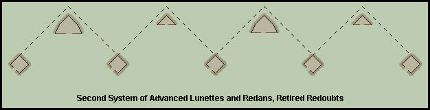
Another system ,described in H. L. Scott's Military
Dictionary, called for an advanced line of works open at the gorge (lunettes
or redans) supported by a second line of irregular shaped redoubts 400 to
500 yards to the rear and positioned to cover the intervals in the first
line. Collateral works were to be within range of each other, between 600
and 700 yards apart, and each was to be capable of an independent defense.
Unlike Mahan's system, there was no prescribed form for the redoubts of the
second line, rather, they were to be adapted to the terrain and capable of
sustaining a strong defensive effort in all directions with their parapets
defiladed by directing the lines of the interior crests toward ground
inaccessible to the enemy.
A third system, described and popularized by D. H. Mahan,
had been developed by French General Rogniat which called for a series of
large lunettes of low profile flanked by small redans and straight curtains.
The capitals of the large lunettes were spaced 250 yards apart with faces
60 yards and flanks 40 yards long. A straight curtain overlapped the flanks
of collateral redans and was broken in the center by a small redan with a
pan-coupe which was positioned to provide flanking fire across the ground
in front of the lunettes' faces. An interval about 10 yards wide was left
between the terminus of the lunettes' flanks and the front of the curtains'
flanks. The lunettes were to be given a profile that included parapets about
five feet thick arranged for defense by infantry and ditches no more than
6 feet deep and 12 feet wide. The curtains were formed from an interior trench
with earth thrown in front to form a parapet about four feet high and arranged
with steps to allow infantry to easily mount the parapet from the interior
of the work. Each redan was constructed as a barbette
battery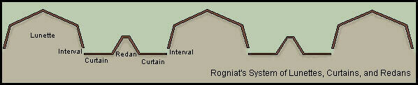 for
field artillery with a low parapet two feet, six inches tall and a ditch
in front only deep enough to provide the earth for the parapet.
for
field artillery with a low parapet two feet, six inches tall and a ditch
in front only deep enough to provide the earth for the parapet.
Rogniat's system offered a sound method for protecting
an army's front with a nearly continuous line of field works while providing
the means for troops to pass over low parapets or through intervals
between the works in order of battle to counter attack the enemy. While
infantry were to advance over the curtains cavalry and light artillery were
to pass through the small intervals between the lunettes and curtains.
Since the advance started from the retired portions of the line the
first troops over the curtains' parapets would benefit from the protection
of troops defending the advanced lunettes. Mahan also believed that the retired
artillery redans would naturally draw the attacking army's artillery fire
away from the more exposed lunettes as the attackers' guns tried to support
the attack by silencing defending batteries. The system , in short, worked
as a regular line with intervals without wide intervals while providing better
cover for the defending army's troops and artillery. Just as important, the
low profile of Rogniat's works meant that they could be constructed relatively
quickly by an army that had all ready assumed its position and order of battle.
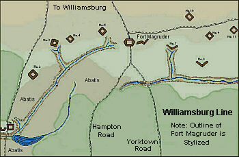
The Williamsburg Line was originally intended as a secondary
position to block the egress of an enemy army from the Yorktown Peninsula.
The redoubts were arranged for reciprocal defense with their faces projecting
columns of fire across the salient angles of collateral works. Two small
advanced redans guarded ravines that might otherwise have been used by an
enemy to approach the line undercover. The interior spaces of the redans
were seen from the main line of redoubts and exposed to their fire. The redoubts
were relatively far apart and seem primarily to have been intended as battery
positions. During the Battle of Williamsburg the redoubts and Fort Magruder
served as battery positions when the Confederate infantry advanced through
the line to attack the advancing Federal army.

The interior line of defense guarding the southern approaches
to Savannah, Georgia contained an interesting combination of linear forms.
Part of the line was composed of 18 detached lunettes and three redans. Most
of the works were prepared for an artillery armament of one gun mounted en
barbette at the salient angles. The lunettes had a relatively strong
profile and the salients were an (estimated) average of about 250 yards apart.
It is not clear why the engineer who designed the interior line chose to
employ a line of detached works, especially since the number of troops available
to defend the line was far too limited to allow the Confederates to risk
a counter attacking defense
The lines of defense for James Island, the primary southern
approach to Charleston Harbor, were established in principle prior to the
time when Major General J. C. Pemberton assumed command of the Department
of South Carolina and Georgia (March 14, 1862) and were positioned with regard
to the Federal Navy's command of the waters exterior the harbor and its presumed
ability to penetrate at will into unprotected coastal waterways.The
Stono River, which formed the southern boundary of James Island, was wide
and deep enough to allow passage of small Federal gunboats and transports.
Unable to amass a sufficient number of heavy guns to both protect the entrance
to Charleston Harbor and block the Stono River, the Confederates chose to
surrender passage of the Stono and establish their line of defense on James
Island at a distance from the river to repel an overland attack. The
line was divided into two sections, the West Line, which connected to the
landside defenses of Charleston, was constructed as a continuous line of
redans which ran from the Wappoo River to the Swamps of James Island Creek.
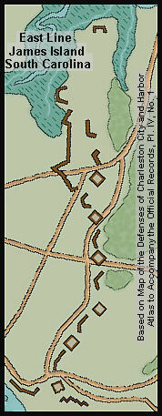
The East Line on James Island conformed to the second system
discussed above. A line of redoubts of strong profile and well armed with
artillery was positioned between the swamps extending from Light House Creek
on the east to James Island Creek to the west. The redoubts were arranged
for reciprocal defense and the artillery armament was positioned at the redoubts'
salient angles. Intervals between the redoubts were covered by a line of
advanced redans the interior spaces of which were seen and exposed to fire
from the redoubts. A line of low rifle pits was placed well in front of the
redans covering the right front of the line. Lines with intervals assumed
that the defenders would have a sufficiently large number of troops to be
able to counter attack an enemy army attempting to force its way through
the line. When the East Line was constructed, the garrison at Charleston
was large enough for a counter attacking land defense, but as troops were
withdrawn and sent to other theaters of action and the size of the garrison
decreased, the East Line began to require an inappropriately large number
of troops to both man the works and provide a strong reserve.
When Major General P. G. T. Beauregard assumed command
of the Department the land defenses of James Island were considered defective
in several important respects. The East and West lines gave up too much ground
on the island and required too many troops to hold adequately defend them.
The East Line was criticized as poorly located and designed since the redans
were thought to block artillery fire from the redoubts. The rifle pits in
front of the right section of the line were thought to be poorly placed since
they would prevent artillery in the retired works from reaching beyond the
line. All of the works were constructed with profiles that were far to strong
to allow infantry to pass over them with ease. Alfred Roman, who served on
Beauregard's staff and mentioned these criticisms in his massive missive
The Military Operations of General Beauregard basically regarded the
East Line as defective because it did not follow Roginat's system. Whether
Roman, an ordnance officer, understood the objective of the system used to
design and construct the East Line is not clear, but certainly the line was
severely weakened by the withdrawal of troops from the Charleston garrison
and the Federal army's decision to limited their operations to Morris Island
and closing the harbor entrance rather than attempting to strike at Charleston
by way of the Stono. The later Federal decision allowed the Confederates
to replace the East and West lines on James Island with a new line farther
forward that had its left anchored on Fort Lamar and the swamps around Light
House Creek.
Back to Major Works
Redan Lines
Tenaille Lines
Cremaillere Lines
Bastion Lines
Contents Home
Page Minor Works
Siege Works
Permanent Fortifications
Glossary
Copyright (c) PEMcDuffie 1998