|
|
DURING recent years the local, and to some extent the main line railway services have experienced growing competition from road passenger transport ; thus a large number of passengers have been lost by the railways. One reason for this state of affairs is that the petrol and oil-engine types of road vehicle can be made much lighter and operated much more economically than the relatively heavy and cumbersome steam train or steam coach. Moreover, the road vehicle can be arranged to work on a more frequent service than the ordinary steam train. The road motor coach or omnibus is usually designed so that the weight of the chassis and body is kept down to the lowest possible figure, whereas with the steam vehicle, owing to the type of construction employed, a considerably greater weight is needed for the same number of passengers carried. Thus in the instance of one particular road coach the weight of the vehicle works out at 300 lb. for every passenger carried. On the other hand, a certain type of steam coach fully occupied gives a weight of 1,000 to 1,200 lb. for each passenger. Evidently, therefore, with the existing pattern steam coaches, it cannot be so economical to carry a person by rail as by road, for not only is the steam coach from three to four times as heavy as a road motor vehicle, but also its first cost is considerably higher. It is well known to engineers that the steam locomotive engine is far less efficient than the petrol engine, for it will generate only from one-fourth to one-fifth the useful horse-power of the latter type from the same weight of fuel used. If the performance of the steam engine is compared with that of the Diesel engine, the discrepancy in the power output is even greater. Although coal is cheaper per pound weight than petrol or Diesel fuel oil, yet the fuel cost of the steam engine is appreciably heavier, amounting to from two to three times that of the petrol engine developing the same power.
The disadvantages of the steam coach are thus rather numerous. It is considerably heavier, and therefore requires more horse-power to attain a certain speed. It also uses more fuel for a given power output than the vehicle having a petrol or Diesel engine. In addition, it has the drawback of larger dimensions for the same number of passengers carried. It also needs a relatively longer period of time in which to generate steam, and the steam pressure must be maintained whether the train is moving or stationary. On the other hand, the petrol or Diesel engine can be started from cold and run within a few minutes of starting up ; as soon as the water in the cylinder jackets is warm the vehicle is able to begin full-load work. In view of the various advantages of the internal-combustion engine it is not surprising that the railway authorities have recently given their attention to the possibilities of adapting road passenger vehicle engines and constructional methods to railway purposes. Their object is to improve rail coaches sufficiently to enable them to compete on level or even better terms with their road rivals. The railway engineer knows that if rail passenger coaches are made in a manner similar to those used on the road services, a large saving in the weight to be hauled is made possible. Further, by using the petrol or Diesel engine instead of the more cumbersome steam engine, a considerable economy in the fuel costs can also be effected. Another important advantage results from the operation of road vehicles on railways. The substitution of plain flanged wheels and smooth, straight railway tracks for road conditions results in a marked reduction in the driving effort required to haul these vehicles on the rails ; there are no road inequalities, rough surfaces, or steep hills to negotiate. Everything, therefore, appears to favour the use of railway coaches built on modern road vehicle lines and propelled by similar engines. In their first cost, and in running costs, they have the advantage of steam coaches ; and they should be able to compete successfully in running and maintenance costs with road passenger vehicles. Incidentally, also, the smaller Diesel rail coach is much more economical than almost any form of electrically propelled train, because of the high capital charges for track electrification.
In these circumstances it is not surprising to learn that several British firms have concentrated upon the design and manufacture of Diesel rail coaches, and that several satisfactory types are now in use at home and abroad. There are also a number of Continental and American rail-cars and Diesel trains in regular service, but the present page will be confined to representative British railway vehicles of the small passenger-coach pattern. In this connexion it has been definitely established that for the transport of from forty to a hundred persons the Diesel rail coach is in most respects superior to the steam-driven trains hitherto used tor this purpose. It should not, however, be assumed that there is any immediate possibility of the Diesel-driven train rivalling the modern steam-hauled train for the transport of a large number of passengers. The efficient steam-driven train, with specially light carriages and adequate streamlining, will doubtless hold its own in this field for some time to come, in the same way as the larger marine steam engine units are claimed to have firmly established their mastery over the Diesel engine. The most favoured types of British Diesel rail coaches are those designed for the accommodation of from forty to seventy passengers at cruising speeds of fifty to sixty miles per hour. The overall lengths of these rail coaches range from about forty to sixty-five feet. The smaller cars are usually fitted with a single six-cylinder Diesel engine, of automobile pattern, giving about 130 to 140 brake horse-power ; the larger cars have two-engine units, or large single engines, of 200 to 260 brake horsepower. The total laden weights of these passenger vehicles range from about thirteen tons for the smallest car to nearly forty tons for the largest.
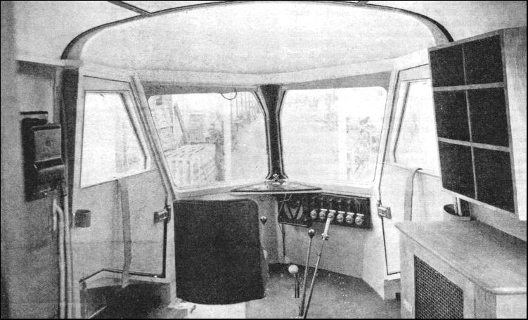
Some idea of the relatively low fuel costs may be obtained from the statement that the smallest rail-cars use only about one pint (costing about 1/2d.) of fuel per mile, while the larger vehicles require about twice that amount. The amount of lubricating oil used is extremely small. There are no "standing" fuel costs when the vehicle is stationary, whereas with the steam locomotive the firebox must be constantly replenished with coal, whether the engine is working or "waiting." Furthermore, there is no need for a stoker on the Diesel rail-car, for the driver can readily attend to everything, so that the wages of the fireman are saved. The designs of all the British Diesel rail-cars have much in common. Some have been designed with smooth streamlined bodies, while others are lighter adaptations of ordinary rail coaches. In all instances, however, there is no separate hauling unit as with the steam locomotive ; for the Diesel engine, being of relatively small proportions, can readily be housed in a fairly small compartment arranged at the end of the coach. In several examples the engine is mounted amidships on the side or central portion of the chassis frame, so that it is well away from the driver ; with this lay-out the driver has only the driving control, brake levers, and gauges in his compartment. The controls include levers for the gear-changing mechanism (or its equivalent), the accelerator, and the transmission clutch, where this is fitted. In rail-cars having the Diesel-electric transmission system, the controls consist of rheostats and switches, somewhat on the lines of those employed on electric tramcars and trolley buses. Everything is arranged for simplicity of speed control, thus allowing the driver to keep a good watch ahead. The braking arrangements have been carefully considered, for, owing to the high rail speeds attained, it becomes essential to be able to bring the cars to rest as quickly and as smoothly as possible. The vacuum brake appears to be the most suitable for this type of vehicle, and it is therefore to be found on most of the different makes of rail-car. In one type of pneumatic-tyred rail-car, the Westinghouse compressed-air system of braking is employed. This is used in conjunction with the automobile type of Lockheed hydraulic brakes, so that a powerful braking effect is obtained.
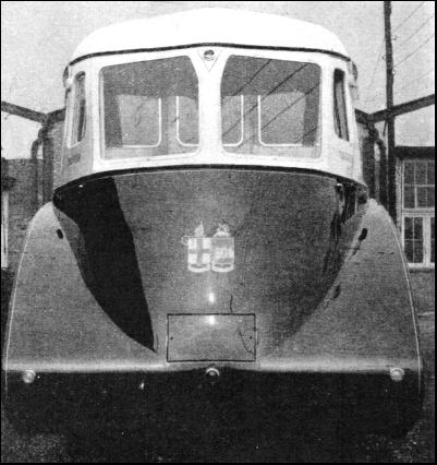
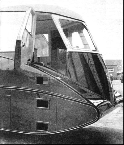
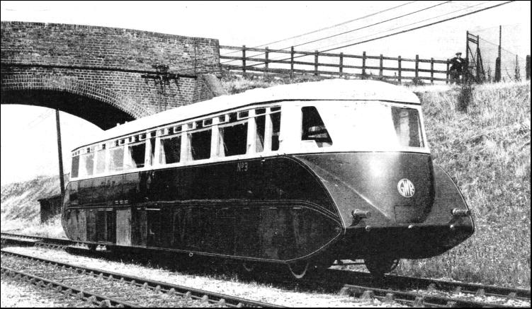
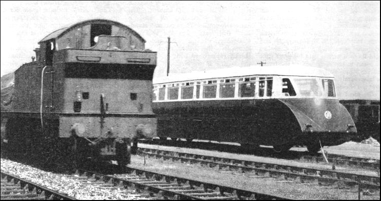
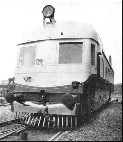
An interesting feature of the Diesel rail-car is the use made of roller bearings for the axle bearings in place of the ordinary gunmetal pattern plain axle-boxes. As the frictional resistance of properly designed roller bearings is only about one-tenth of that of the plain gunmetal type, it is clear that their use will appreciably reduce the amount of power necessary to propel the rail-car. Roller bearings require far less lubrication than plain bearings, and give a long useful period of service before replacement becomes necessary. Where the adjustable taper type of roller bearing is employed, any wear which occurs can readily be taken up in the bearings themselves, so that their useful life is almost unlimited with reasonable treatment. The advantages and the principal features of British rail-cars having been outlined, a number of representative types will be described in more detail. Each of the examples selected has its own particular transmission system and control arrangement ; in this connexion a certain amount of ingenuity has been successfully exercised to attain the desired results. The first of the rail-cars to be described is the A.E.G. single-engine type, designed and manufactured by Hardy Motors, Ltd., a company allied to the Associated Equipment Company, Ltd., of Southall, Middlesex. The latter company supplies engines and chassis for the London Passenger Transport Board, which has absorbed the London General Omnibus Company. This fact is mentioned on account of the adaptation of the London motor-bus engine and transmission system to rail-car use. The A.E.C. rail-car has been constructed with a streamline type of body in order to minimize wind resistance, thus enabling the vehicle to obtain higher rail speeds, with the same engine power, than would be possible with the orthodox shapes of rail coach. The car has the same type of Diesel engine as that employed on motor-buses, namely, a six-cylinder water-cooled vertical engine of the high-speed Diesel pattern ; this engine has a bore and stroke of 4.53 in. and 5.59 in. respectively, and develops 130 brake horsepower at an engine speed of about 2,000 r.p.m. The engine weighs about 1,500 lb. The vehicle measures 40 ft. between the centres of the two four-wheel bogies and 62 ft. overall. If the buffers are included the length becomes 63 ft. 7 in. The height measured from the rails is 11 ft. 4 in., and the overall width 9 ft. The seating accommodation is arranged for sixty-nine persons, and there is a luggage compartment in addition. As many as eighty-eight persons could be carried if the luggage space were dispensed with and more seats provided. The total weight of the chassis is only thirteen and a half tons ; when fully loaded the car weighs twenty tons. This rail-car was not designed for very high speeds, but to give economical services at speeds up to sixty miles an hour. It is therefore more suitable for suburban and branch line services than for long-distance express work. The A.E.C. rail-car built experimentally for the Great Western Railway was put into service early in 1934 on short-distance work in the Slough-Reading area. This car averaged 240 miles a day with some seventy-five scheduled stops. The average distance between the stations was only 3.2 miles, but, even so, the average start-to-stop speed was 35.3 miles an hour. The fuel consumption worked out at eight miles to the gallon.
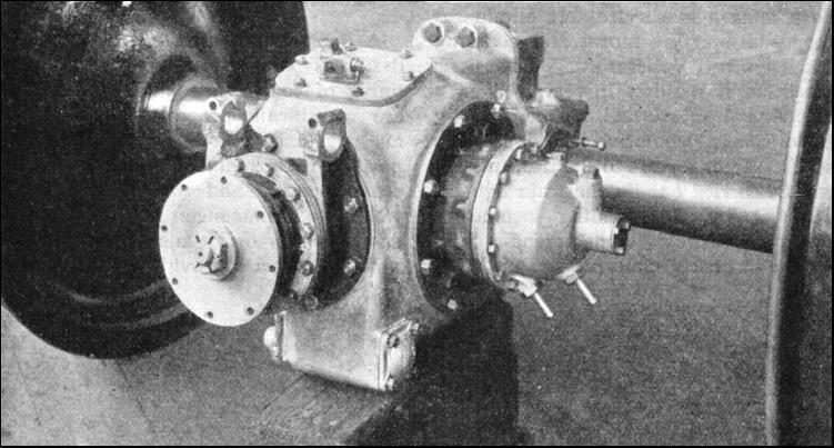
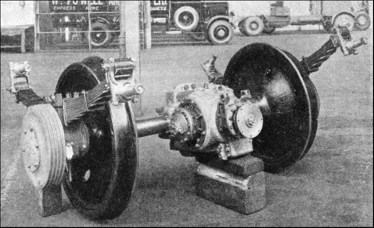
In this interesting rail-car the engine is placed in the central portion of the chassis, but on one side, to provide accessibility through a suitably arranged door in the body. The engine is connected to a special design of gear-box, known as the Wilson pre-selective gear, through a short shaft having metal universal couplings at the ends, and is fitted with the Daimler pattern fluid flywheel in place of the usual clutch found in motor-car practice. This hydraulic type of coupling allows the engine to take up the driving load smoothly and without shock, through the agency of the fluid employed. It is so arranged that when the engine is working at a low speed, say, at about 500-600 r.p.m., the hydraulic clutch is automatically disconnected from the rest of the transmission, namely, the gear-box. Upon accelerating the engine above this speed, the drive is transmitted through the hydraulic clutch to the gear-box. There is thus no necessity for the ordinary friction type of clutch ; nor is any clutch pedal necessary. All that the driver has to do to start the rail-car from rest is, first, to select the low-gear position of the gear lever, and then to speed up the engine from its idling speed, when the rail-car will gradually move forward on its lowest gear. After a certain speed has been attained, the gear can be changed through the higher gears to the directly driven top-speed position. The Wilson gear-box is of an automatic type similar to that employed on the Armstrong-Siddeley and other motor-cars. The principle of this arrangement is that any desired gear ratio can be selected, by means of a small lever and graduated quadrant having the corresponding gear ratio positions marked upon it. The gear ratio likely to be required can thus be selected beforehand. When the pre-selected gear ratio is wanted all that the driver has to do is to depress a foot pedal, known as the "gear change pedal," and release it. The selected gear is then automatically engaged. The hydraulic clutch is here very useful in preventing any shock to the transmission when the gear is changed. The combination of the hydraulic clutch and pre-selective gearbox renders the driving control extremely simple. The gear-box gives four forward speeds and one reverse. Speeds of 14.45, 25.4, 40.25, and 60 m.p.h. are obtainable with this gear-box for an engine speed of 2,260 r.p.m. Beyond the gear-box there is a reverse gear-box to enable the rail-car to travel at any of its four speeds in either direction. A dog-clutch is employed to change from one direction of drive to the reverse. From the reverse gear-box the drive is taken by means of a shaft having universal joints and a telescopic sliding device to the worm-and-wheel drive on the front axle member of the four-wheel bogie unit. The rear member of the latter is also positively driven by means of a universally jointed shaft and another worm-and-wheel unit, from the front shaft. To allow for any differences in the diameters of the driving wheels a differential gear mechanism is provided in the front axle box casing ; this prevents any undue driving stresses between the two axle units. Only one of the two four-wheel bogie units is driven by the engine ; the other is an idle member.
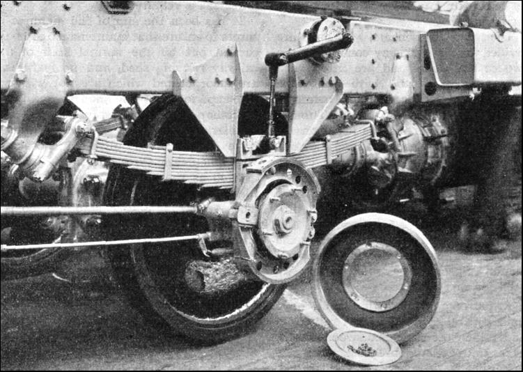
The axles rotate in roller bearings within their axle boxes. The chassis frame weight is transmitted through the usual pattern laminated springs to the tops of the axle boxes ; the latter slide in horn plate guides as in ordinary locomotive practice. The brakes, instead of being of the conventional rim type of shoe brake, are internally expanding brakes of the automobile pattern working inside brake drums. The braking force is obtained from the pistons of vacuum cylinders ; two such vacuum cylinders are mounted on each bogie. The vacuum required for these cylinders is maintained by two exhausters. One of these is mounted on the top of the gear-box and is driven from the output shaft of the latter by means of a chain and sprocket wheels ; the other exhauster is driven from the engine. The wheels are arranged for sanding gear, which is operated by vacuum from the brake supply system. The car is electrically lighted, a large-capacity accumulator being provided ; this is kept charged by means of the engine-driven generator. A conventional self-starter is provided, engaging with a toothed rim on the flywheel of the engine. An important feature of the engine cooling arrangement is the provision of an air-deflecting duct to direct the air in front through the water-cooled radiator, which is mounted in front of the engine. The rail-car is fitted with duplicated controls for the driver, at both ends of the body ; this obviates the necessity for turning the vehicle on the rails, since it can be driven equally well from either end. The controls comprise an accelerator pedal, reverse gear lever, ratchet hand-brake, finger-control lever for the vacuum brake and another for the wheel sanding gear, and the pedal used for the Wilson gear-box. The hand-brake lever at either end of the coach only applies the brakes on the wheels of the bogie immediately beneath it. The two levers are not interconnected. The reverse gear lever and the pre-selector gear lever are, of course, interconnected. A larger type of A.E.C. rail-car, the design of which is largely based on that of the model just described, is also in service. Six of these larger vehicles were ordered in 1934 by the Great Western Railway, and are in regular service. This larger type has two 130 h.p. high-speed A.E.C. Diesel engines, one driving direct and the other through a four-speed pre-selective gear-box. The fluid flywheel is used in each of these engines. Before dealing with the transmission and other technical details, it will be of interest to mention some general facts regarding the vehicle and its general performance. The rail-car is 63 ft. 7 in. long (overall), 11 ft. 8 in. high, and 9 ft. wide (overall), and has a streamlined body resembling that of the single-engine railcar previously described. It has only about one-quarter of the wind resistance of the square-ended type normally used. The four-speed gear-box employed enables speeds of 18, 32, 50, and 75 m.p.h. to be obtained when the engine is working at 2,250 r.p.m. On its demonstration trials one of these rail-cars made a return trip between Paddington and Oxford, in the course of which eight consecutive miles were covered at a speed of 70 to 72 m.p.h. and forty-four miles were run in forty minutes, giving an average speed of 66 m.p.h. Another trial run was made on the Birmingham to Cardiff route, when 117-1/2 miles were covered at an average speed of 56-1/2 m.p.h. The maximum speed attained during the trials was 76 m.p.h. The fuel consumption of this two-engined vehicle worked out at five to five and a half miles per gallon, which, with fuel at, say, 1s. per gallon, gives a remarkably low fuel cost. A public rail-car service was subsequently run between Birmingham and Cardiff, the supplementary charge of 2s. 6d. being made over the ordinary third-class fare.
The general arrangement of this rail-car is as follows. One of the A.E.C. 130 horse-power Diesel engines transmits its power through a fluid flywheel, Wilson pre-selective gear-box, and reverse gearbox to the worm-and-wheel drive on two of the wheels of one bogie unit, in the manner of the single-engine rail-car previously described. The other identical type Diesel engine drives one of the wheels of the other bogie, through a reverse gear-box ; it has no other gearbox. To make quite sure that the two engines operate at the same speed a device is incorporated in the throttle connexion between the two engines, so that the direct drive engine is given a full throttle opening only when in top gear, the opening at starting being about one-quarter. One of the Diesel engines, with its transmission units, is arranged in an accessible position on one side of the chassis, while the other is placed in a similar position on the other side. To provide ample cooling when travelling in either direction the radiator is set diagonally and the air is drawn through it by means of a cowled fan ; this air is collected by one or other of a set of louvers. A hinged plate, automatically operated, ensures that the air stream from the appropriate louvers is directed towards the cowl. The coach arrangements include a compartment at each end in the "nose" of the body for the driver, with space for luggage in the larger one of these compartments. The hot water supply in the lavatories is ingeniously provided by utilizing the exhaust gases of the engines ; this apparatus is the silencing system also, the gases then passing through an exhaust pipe in the roof. There is a buffet, divided across its centre by a counter with four seats facing it. The two passengers' saloons are divided by the gangway connecting the two central doors and are fitted with forty fixed seats and with removable tables. The electric lighting is arranged to give a soft diffused effect. Tubular lights with two bulbs are fitted on the side panels above each seat and the same type of lamp is used down the centre of the roof. Ventilators for extracting the air are placed on the roof and above the windows. Electric fans are provided in the buffet compartment, and a heating system is also installed in the saloons, buffet and driver's compartments. Specially designed heaters are used for this purpose. Armstrong Whitworth, Ltd., have built several types of Diesel rail-coach and rail-car at their Scotswood works, near Newcastle-upon-Tyne ; some are in service both in Britain and abroad. The types with which the present page is concerned are the 250 h.p., 140 h.p., and 95 h.p. designs. In the two smaller rail-cars, the design of the chassis and coachwork is identical, but the choice of engines is left to the purchaser. This type, known as a "rail-bus," is one of the lightest of its kind, weighing only seventeen and a half tons in working order and seating fifty-seven passengers, or seventy-one when no luggage compartment is required. It has been the aim of the manufacturers to ensure that maintenance can be carried out by the normal staff of a railway running shed, and no features are incorporated which are not within the experience of the modern railway workshop using road transport as an ancillary service. For this reason they have avoided the ultra-light coach, with pneumatic-tyres and fabric body, as well as the other extreme of ultra high-speed aeroplane-engined rail-car. The Armstrong-Saurer standard commercial road vehicle engine is employed, which has shown itself able to withstand the extremely rigorous conditions of commercial road service with lower maintenance costs and even greater reliability than the petrol engine. The A.B.E. (patented) transmission is so simple that it requires practically no attention in service. It eliminates the usual starting motor and charging and lighting generator. What little attention it requires in service is of a mechanical nature and can be done by the ordinary locomotive shed or carriage staff. Major repairs to the transmission can be carried out by the train lighting staff or by the existing locomotive works electrical department. This simple electrical transmission has a life at least twice that of any mechanical gear, even when the latter is protected by a hydraulic gear and is self-changing, and its maintenance costs are very considerably less. Bogies of orthodox but light construction are employed. Great care has been taken in the design of the whole vehicle, including the body. The aims have been reliability, safety, and avoidance of high maintenance costs which might follow excessive weight cutting. A most interesting feature of the design is perhaps the effective streamlining of coach ends and sides, which are scientifically proportioned to reduce air resistance to the minimum compatible with making full use of the coach length and width. The tare weight per passenger seat is as little as 0.31 ton or 0.25 ton, according to the number of seats provided.
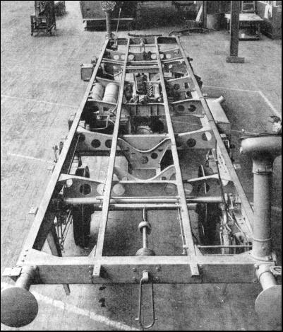
The body provides an example of light road-vehicle construction adapted to the more rigorous requirements of railway service ; this was made possible by the provision of two deep pressed steel underframe members centrally placed, instead of the usual channel solebar construction. The floor framing of oak is flitched with 8-gauge mild steel plate to the pillars, which are also flitched at all important joints with steel plate. The exterior is panelled in 18-gauge aluminium, except the car ends, which are of hand-beaten steel. The fittings are mainly of chromium metal. Half-drop windows in light metal frames are fitted in the passenger compartment, with fixed safety glass driving windows and drop windows in the guard's compartment and driver's cab. Seating is of the most modern "tub" type two- and three-seat pattern, upholstered in moquette over patent rubber cushions. Coach heating is by means of a small radiator through which passes some of the engine cooling water ; a belt-driven fan directs the warm air upwards through a duct to two smaller ducts running the full length of the passenger compartment at the skirting board, and fitted with a sliding louvre between each pair of seats. Passengers may therefore adjust to their liking the flow of warm air issuing from the louvre at their feet.
The power unit comprises an Armstrong-Saurer Commercial Vehicle heavy oil engine, with the same A.B.E. patented transmission as is used on all the range of Armstrong Whitworth 15-ton to 30-ton shunting locomotives. The selection of the A.B.E. transmission is adduced as a proof of the claim that the advantages of a completely flexible and constant horse-power electric drive can be obtained without sacrifice of lightness, and without increasing the initial cost of the vehicle. The feature of constant horse-power amply compensated for the rather higher efficiency of the gear-box which, however, can only make the best use of the engine at its two or three fixed working speeds. The 95 b.h.p. and the 140 b.h.p. Armstrong-Saurer Diesel engines are both of the six-cylinder type, running at maximum speeds of 2,000 and 1,500 respectively. Three-point support of the power unit in rubber "silenbloc" bushes is used, as on the road vehicle ; but in addition a carefully designed laminated spring suspension prevents any trace of vibration from being transmitted to the chassis. The usual electric starting motor and lighting dynamo are both replaced by the A.B.E. generator, bolted on to the crank-case in place of the usual gear-box, while the final drive is by a traction motor rigidly mounted in the underframe, cardan shaft, and Craven-Guest worm drive. Engine cooling is effected by two radiators, one at either end of the car, mounted opposite an opening in the streamlined skirting.
The control fitted to this rail-bus, from the driver's standpoint, approximates to the steam locomotive pattern. Three levers, working in a slotted cover, operate the throttle, the forward and reverse drum, and the engine stop and start switch, the necessary apparatus being for simplicity and economy incorporated in one set (instead of the usual two sets), situated near the engine and controlled by compensated heavy-duty steel wire rope running on pulleys. A lightly operated "dead man's button" fitted to the end of the throttle handle allows perfect safety with one-man operation, without causing any fatigue or inconvenience when driving. A departure has been made from the usual railway type of braking, in the adoption of Ferodo-lined expanding shoes, which work in brake drums mounted on the inside of the running wheels ; the four brakes of each bogie are actuated by a small compressed-air cylinder, linked with the hand brake rigging of the rear driver's cab. Rise and fall of the axle in the horn guides are permitted by allowing the expanding brakes to ride on lubricated bushes on the axle. A small standard motor-driven Westinghouse air compressor keeps the reservoir automatically filled to the correct pressure. The "dead man's button" on the throttle lever, if released inadvertently, applies the brakes in addition to cutting off power. A passengers' emergency brake valve is situated in the vestibule.
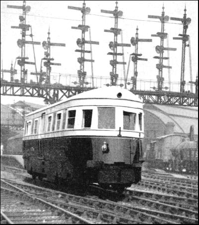
The English Electric Company's rail coach, designed primarily for branch-line working, is built generally on ordinary rail coach lines, but lightened in many respects. It measures 62 ft. 10-1/2 in. in length over the buffers and 59 ft. 6 in. over the body. The overall width is just under 9 ft. and the height just under 13 ft. The ordinary seating capacity is arranged for fifty-three persons ; the maximum seating capacity is sixty-one. The weight of the rail coach, in working order, but without passengers or luggage, is 37-1/2 tons. The rail coach is fitted with a six-cylinder vertical type high-speed Diesel engine, delivering 200 h.p. at 1,500 r.p.m. : the engine can give a maximum output of 220 h.p. for short periods of about fifteen minutes' duration. When the engine is idling its speed is 600 r.p.m. The maximum speed of the rail coach is about sixty miles an hour. The engine is direct-coupled to an electric generator of the 135 k.w. type, built and rated in accordance with standard electric traction practice. The electric supply from this generator is used to operate two axle-hung electric motors on the two-axle bogie unit arranged under the engine compartment. The other two-axle bogie unit is a trailing member. It is built up of steel sections, and both bogies are fitted with roller-bearing axle-boxes.
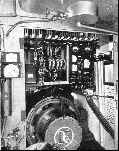
The coach has five compartments—the engine-room, a driving compartment at either end, the passenger compartment, and a luggage-room. The engine-room, which is of steel construction throughout, is separated from the passenger compartment by the luggage-room ; the bulkhead on the side nearest the passenger compartment is lined with a special sound-deadening material so that no engine noise reaches the passengers. The roof of the engine-room can be removed to enable the power unit to be lifted out bodily for major overhauls. The interior finish of the passenger compartment is of polished mahogany, with mahogany mouldings and chromium-plated metal fittings. The seats are upholstered in figured moquette and have removable cushions. Access to this compartment is afforded by a central entrance controlled by sliding doors, as in underground electric train practice. At the trailing end of the coach the partition separating the passenger and driving compartments is of glass from above the waist-line. In effect, this gives the advantages of an observation saloon, since a view can be obtained through the end of the coach. Blinds are arranged to cover the window for night driving. The coach is provided with a vacuum brake operating on all wheels. A screw-down hand-brake operating through the power brake rigging applies a brake on the driving bogie wheels. An electrically-driven exhauster is provided ; this is located in the engine-room compartment. The engine-driven electric generator has a separately mounted chain-driven exciter. The engine and generator unit are carried in trunnion bearings, arranged so as to give a three-point suspension system. In this way stresses are prevented in the crankcase or crankshaft due to any strain or whipping of the coach underframe ; the usual massive engine bed-plate is thus unnecessary. The power unit bearers and their fixing bolts are insulated from the underframe with rubber ; this reduces to a minimum any noise or vibration transmitted along the coach. The control equipment, comprising the reverse, motor contactors, and the battery automatic cut-out apparatus, is grouped together and mounted above the generator.
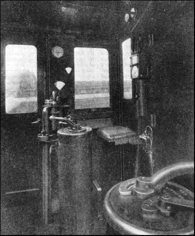
The engine compartment requires no attendance during running. The vehicle is arranged for one-man operation. Control is extremely simple, and drivers quite new to this type of vehicle have been able to take over control after less than one hour's tuition. Driving a Diesel rail coach is simpler than driving a road motor vehicle, as there is no steering wheel. The engine is started by operating a push-button switch, one of which is located in each driving compartment. This sets up the circuit between the generator and the battery, and the generator runs as a motor and drives the engine, until the latter starts and takes on the drive. After starting, the master controller gives complete control of all operations, advancing the engine speed from idling to 1,500 r.p.m. in three steps, and finally weakening the traction motor field ; by moving the handle of the master controller backwards the engine speed can be reduced, but the weak motor field condition is retained until the idling position on the master controller is reached. Thus economy of engine power, combined with maximum electric output, is obtained. Further economy in running costs can be secured by moving the master controller handle to the engine shut-down position during coasting periods and when standing in stations, etc. It should further be noted that the engine can be shut down by the master controller, which has the usual "dead man's button" incorporated. Excessive overload currents are prevented by the arrangement of the generator windings and by control of the excitation ; and thus the engine itself cannot be overloaded. The full power output of the generator is automatically maintained constant over a wide range of train speed ; it is therefore unnecessary for the driver to watch any instruments while driving. A set of signal lights, consisting of two red and two white lights, is provided in each driving compartment. The white lights indicate that the pressure of the lubricating oil is adequate, and that the water circulation is correct. The red lamps glow to give a warning signal in the event of failure of oil pressure or of water circulation, and also to indicate when the engine is shut down. A rail coach of this type has been in operation under service conditions on various sections of the L.M.S. Railway system. The first period of running began in October, 1933, on the Weedon-Daventry-Warwick branch line. The coach ran as a single unit carrying passengers, or with trailing loads such as cattle trucks, horse boxes, etc., as required. Vehicles of the type described are capable of working twenty-three hours a day ; but during this period the coach was in service only fifteen hours a day for five days a week. During the five weeks ended November 11, 1933, the rail coach ran 5,880 miles with an average engine fuel consumption of 6.26 miles per gallon.
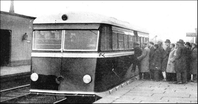
Subsequently the coach was coupled to a standard railway trailer coach and put into service on the Watford-St. Albans route. It was then transferred to the Derby district, where it ran on the Burton-Tutbury line. By March, 1934, the coach had completed six months of service running and had covered 19,000 miles. It was then carefully inspected, for the engine had by this time run for some 2,000 hours. The general condition of the engine was found to be excellent, there being no appreciable wear. Only light grinding of the valves was necessary. The heating arrangements are interesting. A low-pressure steam supply is obtained from an oil-fired boiler, the burner for which uses the same fuel as the engine. After circulating through radiators fitted under the seats in the passengers' compartment, the steam is returned in the form of condensed steam water through a feed tank. Standard hose-couplings are fitted at each end of the coach so that steam can be supplied to any standard steam-fitted passenger coach which it may be desired to use as a trailer. Another interesting design of Diesel rail coach is that constructed by Leyland Motors, Ltd., for the London, Midland and Scottish Railway. This is a lightly built single-unit coach having an overall length of 41 ft. 1 in., a width of 9 ft., and a height of 10 ft. 7 in. The seating capacity is forty. The tare weight is 10.5 tons, and the fully-laden weight 13.1 tons. The coach has only two axles, one of which is power-driven from a Leyland high-speed Diesel engine, developing 130 h.p., operating through an ingenious hydraulic transmission device known as a "torque converter." Before describing the transmission system, it may be of some interest to refer to the performance of this small rail coach, expressed in its acceleration figures. In view of its relatively high power and light weight—which works out at about 590 lb. per passenger carried as against over 1,000 lb. in corresponding steam coach practice, good acceleration would naturally be expected. This expectation is borne out on the track ; for the vehicle has between three and four times the acceleration of the steam rail coach. Thus it can attain a speed of twenty miles per hour from rest in eleven seconds, and fifty miles per hour in forty-nine seconds. The maximum speed is sixty miles per hour, and the fuel consumption is thirteen miles to the gallon. Thus forty passengers can be carried at a total fuel cost per mile of less than one halfpenny. The radius of action possible with the fuel capacity provided is about 200 miles.
Reverting to the subject of the transmission, the employment of the hydraulic torque converter is a big factor not only in the attainment of the very high acceleration of this rail-car, but also in simplifying the driving controls. The engine is mounted in the middle part of the underframe, and has its torque converter built integrally with the engine unit. The torque converter consists essentially of a centrifugal pump mounted in a single casing with a three-stage hydraulic turbine. Its purpose is to multiply the engine torque and to vary this, automatically, in accordance with the speed required by the operating conditions. The driver of the coach is therefore concerned only with regulating the speed of the engine by means of the usual engine control. It should be understood that this torque converter is not the same as the "fluid flywheel," referred to on the early part of this page ; for it replaces the latter as well as the pre-selected gear-box. There is thus no gear-box needed with the torque converter, all the speeds required being automatically given by the latter. Instead, however, of arranging for the top speed of the vehicle to be obtained through the agency of the hydraulic torque converter, the latter is cut out altogether by means of a dual clutch device ; this obviates the hydraulic transmission losses which otherwise would occur and gives a positive mechanical direct drive on top gear. From the hydraulic torque converter the power is transmitted by means of a propeller shaft through a reversing gear mounted in the casing of the driven axle. Spiral bevel pinion wheels are used to take the drive from the propeller shaft to the axle. The reversing gear mechanism is actuated by means of a double-acting vacuum cylinder, controlled by magnet valves operated from a switch on the driver's control column. The latter is very compact and is duplicated at either end of the coach. It has two small levers at the front to control the engine throttle and the power-brake. In the centre there are a change-over switch for the reversing gear and a change-over switch for the electro-pneumatic control of the torque converter to give neutral or direct drive. Around these are arranged two press-buttons for starting and stopping the engine and switches for the lights, horn, windscreen wiper, etc. The throttle and brake levers and torque-converter switch levers are removable and are carried from one control column to the other, so as to prevent interference by passengers. The body of the coach is arranged with the passengers' entrance at the centre, the seats being arranged in pairs on either side of a central gangway. A larger type of rail-coach built by Leyland Motors, Ltd., is fitted with two Leyland Diesel engines and torque converters. This rail coach is capable of hauling two specially constructed light trailing cars. The seating capacity of the rail coacli is eighty-four, and that of the two trailers is eighteen first-class and 176 third-class passengers, making 278 passengers in all. This coach was placed in service on the Belfast-Larne line to provide an accelerated service over various parts of the twenty-four mile route from Belfast to Larne Harbour. It was booked to cover 195 miles every weekday except Saturday, when the mileage was 105. The maximum working speed was fifty-three and a half miles an hour, and a very much better local service was made possible than that formerly provided. The efficiency of modern Diesel rail-coaches has been proved by exhaustive tests. Their use on secondary services may help to check the modern practice of closing branch-lines which have become unremunerative.
Many thanks for your help
|
   Share this page on Facebook - Share  [email protected] |

