|

|
HAULAGE by rope and pulley has been known since the earliest days, and although no graphic record is available, the evidence has been furnished by wooden pulleys found during excavations in Egypt. These pulleys date from about 2600 B.C. One of the oldest pictorial documents of rope haulage is an Assyrian bas-relief representing the siege of a fortress. It was discovered by Sir Henry Layard when he brought to light the ruins of the famous city of Nineveh, and is now in the British Museum. It shows a soldier in the act of cutting a rope to which a bucket is attached, and which is apparently used by the besieged people to draw water from outside. There are several old prints in existence which show that the Chinese used a stretched rope as a means of transport. In one of these prints a man is seen standing in a basket suspended from a rope stretched across a narrow river and hauling himself by his hands along the rope. The first practical aerial ropeway of which there is any definite evidence was devised by Adam Wybe, a Dutch engineer. During the construction of a fort at Danzig he used an aerial ropeway for the conveyance of earth from a hill outside the fortifications to the fort under construction. An endless rope, attached to which was a number of small buckets, ran between the two terminal points and was supported by intermediate standards. The buckets were filled at the hill and travelled on one side to the fort, where they were emptied and returned on the other side back to the hill. The rope ran round pulleys at both terminals and was driven by hand. The same method, adapted to meet modern requirements, is still largely used and is known as the mono-cable system. Although earlier patents had been taken out for aerial ropeways, the first practical and successful patent was granted to Charles Hodgson—an almost forgotten engineer—in 1868. In 1870 Theobald Obach, an Austrian engineer, invented the first practical coupling attachment for the suspension of the carrier from the rope, and thus solved one of the main problems of aerial rope transport. From that date various firms in England and on the Continent began to specialize in this particular industry. Considerable technical difficulties had to be overcome, and because of these, more than forty years passed before aerial ropeway transport was made sufficiently safe to build a passenger-carrying ropeway. It was an Italian firm, Ceretti and Tanfani, which, in 1912, constructed the first passenger ropeway, the Lana-San Vigilio in the southern part of Tirol, which then still formed part of the Austrian Empire. At that time there were no by-laws regulating the construction and working of aerial ropeways for passenger service. The Austrian Government was therefore compelled to create such by-laws to protect passengers. The framing of these by-laws presented many new problems to the authorities, and it took three years to build the railway because of repeated intervention by the Government.
Since then an ever-increasing number of aerial passenger ropeways has been constructed in every part of the world. This is probably due to the large number of ropeways which were built during the war by the Italians. It is estimated that about 1,200 miles of ropeways were built for military purposes during the war on the Italian front and used largely for the transport of troops. The improvements which have been made in the construction, and particularly in the introduction of a number of safety devices, have rendered aerial rope transport absolutely safe. The use of aerial ropeways offers many advantages, the most important of which is that they can do work which for technical or economic reasons other forms of transport cannot do. There is nothing spectacular about an aerial ropeway. It has no vast stations, no mighty trains that make the earth tremble. A few trestles, a few ropes— almost invisible at a distance—an insignificant building at each terminal, and at intervals a cage-like structure sliding gently along the rope. And yet whole districts like the Alps owe their flourishing state to this modest contrivance, which attracts hundreds of thousands of visitors during a season ; many mining undertakings and quarries would never have been able to operate successfully without the adoption of the efficient and inexpensive aerial ropeways. But although this means of transport may seem to be simple and toy-like, it represents a difficult modern engineering achievement. A great engineer has said : "It is no exaggeration to say that an aerial ropeway constructed to the rules of the Art presents greater difficulties than the design of a steam engine." The aerial ropeway has the unique advantage over all other systems of transport that it is not limited by any obstacles or limitation of the ground. Even aeroplanes require flying grounds for taking on and landing, but the small space required for the terminal station can be hewn out of the rock even on the most barren mountain slope. A railway requires in the first instance the preparation of the ground, the boring of tunnels, the cutting of trenches, the construction of embankments, the building of bridges and viaducts. The initial outlay for an aerial ropeway is very small in comparison with that required for the construction, of a railway or a road, and does not increase in proportion to the length. In fact, assuming that the construction of an aerial ropeway would cost £3,700 for half a mile, the cost in equal conditions for a miles would be £7,500, and for 5 miles £15,500. This is accounted for by the fact that the most expensive part of the installation is the driving machinery, the cost of which does not alter within certain distinct limits and never increases in proportion to the length of the line. The maintenance costs and working expenses are small, and even on long lines often amount to only a few pence per ton. Aerial ropeways may be divided into two main categories—the first where one endless travelling rope supports and moves the carriers ; the second, where a fixed carrying rope is employed in conjunction with a moving hauling (or traction) rope, which is firmly attached to the carriers by means of special couplings. Each of these two categories comprises various systems, but the main principle of each always remains the same. The first category, called the mono-cable system, is the one employed at Danzig. The endless steel rope runs over roller supports mounted on standards and over the sheaves of a pulley installed at the terminal stations. The pulley is mounted on a vertical axle and has a diameter of 6 to 10 ft. One of the pulleys is connected with the driving machinery, which is usually operated by electricity. The pulley at the opposite terminal is equipped with a tightening gear which keeps the rope properly stretched. The standards are placed at intervals varying from 200 to 300 ft., and the capacity of the carriers varies between 5 and 10 cwt.
The carriers are hung on the rope by means of saddles consisting of an iron frame which, by the interposition of blocks of wood or other suitable material, adheres to the rope sufficiently firmly to remain in position. A pivot arrangement assures the vertical position of the carriers over gradients. At the terminals, where the carriers have to be loaded or unloaded, rails are mounted on supports at a height which is slightly below that of the ropeway. A special wheel-device is fixed to the saddle and runs on to the rails, thereby lifting the saddle itself so that the carrier becomes free to continue its course on the rails. In many instances the rails are laid on a down gradient, so that the carriers can travel by themselves over a short distance until they reach the place where they are loaded or emptied. They are then brought, full or empty, by rails to the other side of the pulley, and the same wheel device makes them engage the ropeway. The installations for loading and unloading operations at the terminals are constructed for each individual ropeway according to the nature of the materials or goods, to the load capacity of the carriers, or to the hourly capacity of the ropeway. The mono-cable system has the great advantage of economy in the initial outlay, and is much simpler in operation than the bi-cable system. It is particularly suitable in districts where native labour only is available. On the other hand, the capacity of a mono-cable ropeway is limited, and 150 tons an hour is probably the maximum capacity that has been attained. The system itself, like that of any other aerial ropeway, offers so many varieties in construction and lay-out that only the description of a number of existing lines could give a full picture of the many uses to which aerial ropeways in general are put in every part of the world. It should be clearly understood that what has been said before, so far as the distances between standards are concerned, the capacity of carriers and the diameter of the pulleys, should be taken as referring only to a standard average construction. There are mono-cable lines where the distance between standards is as much as 2,500 ft. along the line, and in one instance a clear span of 3,600 ft. is negotiated. The longest line built on this system is believed to be that in Colombia. Its length is 46 miles, and the line is divided in 14 sections, as it would be impossible to have one uninterrupted endless rope, which would have to be more than double the length of the line. In this example, as in all other examples where the line must be divided into sections on account of the length, each section represents an independent unit between two section stations. In each of these intermediate stations the conveyance of the carriers from one rope to the continuation rope is effected over rails in a manner similar to that described for the terminals earlier in this article. The bi-cable system is characterized by the use of two steel ropes, one of which is fixed and carries the load, while the other rope moves, with the carrier firmly attached to it by a special coupling device. The carrying rope may be compared with the rails of a railway line. The bi-cable system has considerable advantages over the single-cable system. Because of its greater capacity and better adaptability for loading and unloading conditions, it is used to a greater extent than the single-cable system, and because of its safety it is also used mainly for passenger transport. The general principle of the bi-cable system is of some interest. The carrying rope is anchored at one terminal and kept tight by means of a tensioning device at the other terminal. The carriers are fitted with grooved wheels of dimensions that vary according to the weight or size of the load. The second rope is fixed to the carriers by a coupling device. Both ropes are supported at intermediate points by trestles, which are equipped with rollers in order to reduce friction. This general principle of the bi-cable system has been adapted in several ways to suit particular requirements. Two types are generally used. In one, there are two fixed carrying ropes running parallel to each other about 8 ft. apart. The traction rope is endless and is operated at one end. On arrival at the terminal the couplings are automatically detached and the carrier runs along rails.
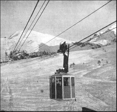
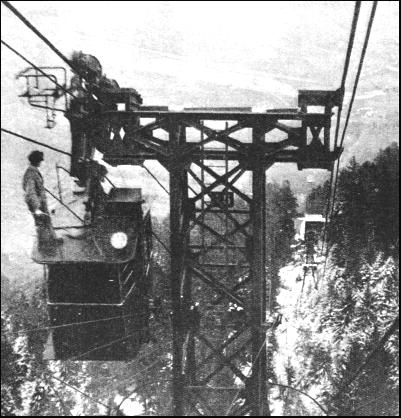
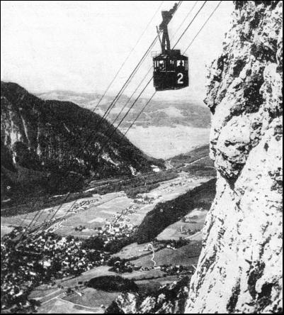
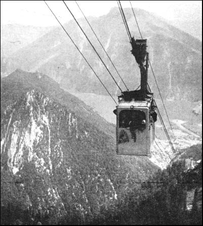
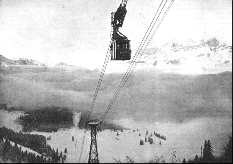
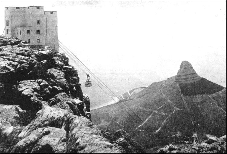
The second type is used for passenger ropeways. The carrying ropes are also running parallel, and usually one carrier is running on each side in opposite directions. The carriages leave both terminal stations simultaneously, pass each other midway, and arrive at the respective terminals at the same moment. Various brake systems are used, the principal one being an automatically acting device attached to the carriage, which grips the carrying rope and brings the carriage to a standstill. As a further precaution a second, auxiliary, traction rope is sometimes used, which in the event of a breakdown acts automatically. This type of ropeway is also largely used for the transport of heavy single loads. The carriages usually have a seating capacity for 24 passengers, but on some lines as many as 36 can conveniently be carried in each carriage. In order to ensure smooth running and a better distribution of weight, passenger carriages are suspended by eight or more wheels arranged in pairs mounted on swivelled frames. The speed is usually 12-16 ft. per second, so that high altitudes are reached within a few minutes. It takes only five minutes to reach by a single span the top of the Table Mountain at Cape Town and to negotiate the difference in altitude of 2,300 ft. The ropeway near Reichenhall in the Bavarian Alps reaches an altitude of 5,160 ft. with a rise of 3,610 ft. in nine minutes. The aerial ropeway which ascends the Kohlerer Mountain in the Austrian Tyrol is one of the most remarkable aerial ways in the world. The aerial railway begins at Eisack, and climbs up the side of the mountain for a distance of 5,250 ft. This distance is not covered in a single span. Twelve lattice steel towers were erected at varying intervals to support the track. The latter consists of steel ropes, each about 1-3/4 in. in diameter, and set some 19-1/2 in. apart. There are two tracks, one for each of the two cars operating. The railway is run on the counterbalancing system. At the upper terminal the ropes are secured to the mountain side, while at the lower end they are connected to heavy weights, placed in a pit, so that the tension shall be maintained. There are two hoisting ropes attached to a travelling truck, or overhead gear above the car itself, which is fitted with four wheels, two running on each rope. The steel towers supporting the track are of heavy construction, built on solid foundations. Their height varies from 23 to 97-1/2 ft. according to the contour of the mountain side. The ropes over the towers are carried upon supporting brackets specially devised so that no jar or oscillation is imparted to the car as its wheels pass over the towers. The travelling speed is generally 10 ft. per second, and the journey occupies nearly thirteen minutes. The railway is electrically operated. Electricity is drawn from a neighbouring power station. Since the railway works upon the counterbalancing system, a large amount of additional power is not required. An electric motor drives a wheel, to which is coupled the cable sheave or pulley. The cable is wound round this several times. In this manner the drive is as direct as possible, and there are three independent brakes, so that the car is always under perfect control. The car itself is suspended from the overhead gear or travelling truck in such a way that it maintains a horizontal position irrespective of the gradient. The car is fitted with large plate-glass windows, and its sixteen passengers have magnificent and uninterrupted views from their seats. The roof of the car is flat, and the driver has access through it to the travelling truck should anything go wrong or need attention on the truck or the track ropes.
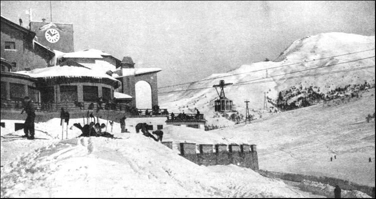
The braking system is designed to ensure perfect safety. If a hoisting rope should break there is a powerful clip which automatically grips the track, and so brings the car to a standstill. This emergency device is so powerful that during the trials, when one of the hoisting ropes was deliberately broken, the car slipped back only six inches before it came to a stop. Even if one of the track cables snapped, the brake would instantly come into operation, and after the car had been stopped it could be restarted and driven slowly into its station along the remaining cable, which is tested to withstand several times the weight of a car. This brake is not only automatic, but can also be applied by the driver, so that whatever should happen it is impossible for the car to slip out of control. At the same time the stations are fitted with automatic and hand-operated brakes to guard against every contingency. such as the failure of the power supply, the breakdown of the machinery or some mishap on the track. There is also an accumulator battery, capable of running the railway for several hours continuously should the main supply fail. It this also failed while cars were running on the track they could be wound in by hand, either with the passengers inside or after an emergency car had been sent down the track to take them off. Even these safety devices are not considered to be sufficient. In the most unlikely event of the failure of all these devices, passengers can still be taken from the car. As emergency apparatus, each car carries a collapsible bag with a rigid bottom. The bag can be lowered through a trap-door in the car-floor, a passenger standing erect within it. A braking gear controls the transit of passengers to the earth, so that the descent shall not be too rapid. The travelling speed of this cable-way is rigorously restricted by the authorities, and expedients have had to be introduced to keep the speed within prescribed limits. There is a speed regulator, set to the permitted maximum. The moment the car, either in ascending or descending, exceeds the speed, the automatic brake comes into action and checks the rate of travel. The authorities have also forbidden the operation of the railway during high winds. A wind-speed indicator is mounted on the roof of the upper station on the mountain. This indicator is connected to a bell signal. Directly the wind exceeds a certain speed, to which the apparatus is set, the bell warns the mechanic to suspend the service. In point of fact, however, there is no danger of high winds affecting the safety working, but the official regulations have to be observed. When passengers travel on this aerial railway they will notice a complete absence of vibration or swinging of the cars. The vehicles start without any perceptible jerk and glide steadily and smoothly up and down the side of the Kohlerer Mountain. When the cars approach a station the speed is automatically decreased and the transit ends as easily as it began. In addition to the telephone and electric lighting circuit between the stations for the transmission of the starting signals, a special telephone wire is provided for the convenience of the driver of the car. The driver is thus in continuous communication with both upper and lower stations during a journey. Should any slight mishap occur, he can immediately notify the engineers at both ends. Another interesting example of a passenger ropeway is that of the Sestrières Pass to Monte Sises in Piedmont, Italy. This line is built in two sections, with an intermediate station. The upper terminal is situated at an altitude of 8,200 ft. This particular aerial ropeway is a typical example of the possibilities of developing a certain district. The mountains near Sestrières offer such wonderful opportunities for winter sport that it became necessary to construct, within two years, a second aerial ropeway to the Banchetta Crest. Perhaps the most notable of the ten Austrian cable railways is the one which ascends the Feuerkogel Mountain in the Höllengebirge range. The railway soars up from the banks of the Traunsee Lake, and its terminus lies some 5,314 ft. above sea level. From the Feuerkogel the traveller can enjoy a splendid view of the Danube valley right away to the dark woods and forests of Bohemia. Austria is the proud possessor of several cable railways, apart from the Feuerkogel line. In Carinthia, by the Ossiacher Lake, a railway has been taken 4,920 ft. up the Kanzel Mountain. At the famous pilgrimage town of Mariazell there is a wonderful cable-way that takes ski-enthusiasts 4,155 ft. up into the much-frequented Burger Alp district. Innsbruck, also, has two cable railways, while not far away there is another at Zell am See on the Schmitten peak.
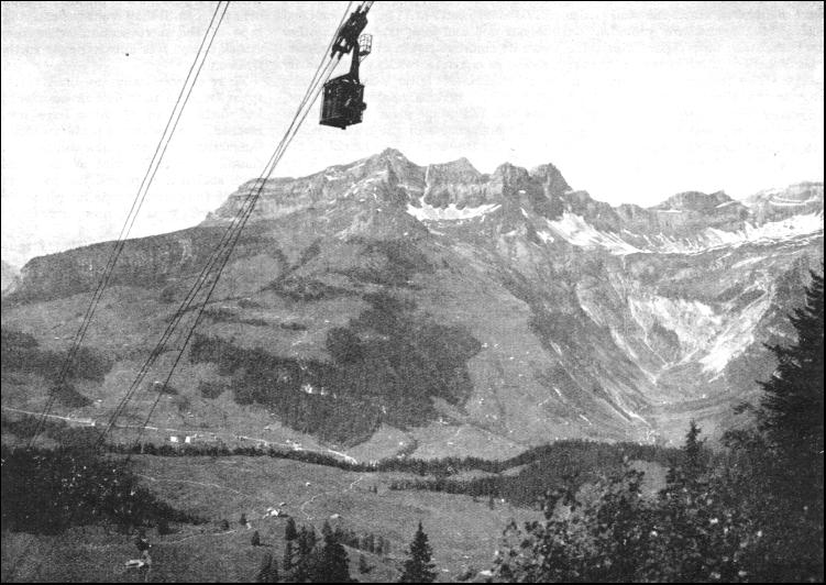
Although the true mountaineer despises the cable-ways as a too-easy manner of sight-seeing, these unique railways have enabled other people to enjoy panoramic views in the Austrian Alps hitherto inaccessible to the untrained climber. The railway authorities have also endeavoured as far as possible to prevent the cable railways from disfiguring the beautiful landscapes. Another interesting aerial ropeway, running in a horizontal direction, was built in 1931 at Barcelona for the purpose of connecting two quarters of the town that are separated by the port. This ropeway has an intermediate station, which is built on one of the quays of the port and which has a height of 350 ft. This ropeway is also noteworthy for the fact that four carriages are running simultaneously, two in either direction. That the aerial ropeway can be adapted for the transport of all kinds of loads may be seen from the large number of carriers constructed for the different types of loads. The principal characteristics of the coupling device remain the same in all systems. The hangers themselves may be differently shaped, and the carriers are sometimes represented by a cradle or double sling for carrying sacks, by chain slings for casks, by platforms for various packed merchandise, by drums for liquids and the like. Where sawn timber or logs are to be transported, two C-shaped carriers are used for holding the long pieces. Sometimes no carriers are used, but the load is merely chained to the hanger ; this was done when Beachy Head lighthouse was built. Then a ropeway was constructed to connect the top of the cliff with the building yard laid out on a stage in the open sea. The bi-cable system has been developed to such an extent that 500 tons an hour can be transported by it, and individual loads up to 20 tons can be carried down gradients of 1 in 1-1/2. An aerial ropeway handling blocks of marble up to 20 tons is used by an English firm that owns quarries near Carrara in Italy. This ropeway is of exceptional interest from a technical point of view, and is an economic solution of many transport problems. The profitable working of marble quarries frequently depends on the cheapness of transport, and this is particularly important when quarries are located high up in the mountains, sometimes at altitudes of 5,000 ft. and higher.
At Carrara the difficulty lies in the fact that the Sagro valley, where the quarries are situated, lies at an altitude of 3,000 ft. and ends abruptly in a precipice of 1,500 ft. high. A ropeway had been in existence before, but its capacity was limited to loads of 6 tons. Heavier blocks had to be transported into the valley below over dangerous slipways, which were cut out on the slopes of the mountains ; thirty and more pairs of oxen were required to haul heavy loads placed on sledge-like trolleys. This system was a slow one, and at the same time expensive, because a large number of men had to be employed. The British firm owning these quarries—where a particularly fine quality of marble is found—decided to entrust one of the principal Italian firms of ropeway constructors with the task of connecting the top of the precipice with the valley below by an aerial railway capable of transporting single loads of 20 tons. The line has a length of 5,250 ft., and the difference in level between the two terminal stations is 2,060 ft. There are four spans, the longest of which is 3,770 ft, The bi-cable system of the "Jig-Back" type was adopted. This is self-driven, as the weight of the descending load hauls the ascending load on the other side. For the down transport two carrying-ropes are used, on which the carrier itself runs. For the up transport one carrying-rope has been installed with a carrier of 10-ton capacity. The carrying ropes on the two sides have a diameter of 2-3/8 in. and are constructed of 19 strands each of 12 crucible-steel wires. The traction rope has a diameter of 1-13/16 in. and consists of 22 crucible-steel wires over a hemp core. Special provisions were made for the anchorage of the traction ropes. These are fixed at the top station to an iron structure, which is embedded in a single concrete block weighing 700 tons and which is keyed by reinforced concrete to the concrete foundations of the station building. The total weight of this anchorage is 2,000 tons. In order to keep the traction ropes taut, each carries at the lower end a counterweight of 60 tons, which hangs on steel chains in a pit 60 ft. deep, hewn out of the rock. These counterweights move with the movement of the load and counteract the pressure of the load upon the carrying-ropes between the trestles. This pressure is naturally a considerable one, as may be judged from the fact that, whereas the sag of the unloaded carrying-rope in the widest span is 98 ft., the sag of the loaded rope is 312 ft. Although the plant is self-driven, a 50 h.p. motor has been installed for starting and to deal with the variation in the down and up loads. The carriers for 20-ton loads run on the two carrying-ropes and are provided with eight pairs of steel wheels. The hanger consists of a heavy steel structure of triangular shape, reinforced by a vertical central post, and is pivoted to the carrier so that it always maintains its position. The three intermediate trestles supporting the carrying-ropes, as well as the trestles at the two terminal stations, are of the steel girder archway type, and are provided on top with steel shoes upon which the ropes rest. The traction rope runs over pulleys. The trestles are anchored in heavy concrete foundations.
Another interesting type of aerial ropeway for the transport of minerals is that from Durcal to the port of Motril on the Spanish coast. The ground traversed is mountainous and rocky, and the costs of construction of a railway, or even a road for carts, would have been prohibitive. Durcal lies at an altitude of 2,560 ft. above sea level. The length of the line to Motril is 22 miles. The line is constructed on the bi-cable system and has a capacity of 300 tons per hour. The carrying-ropes have a diameter of 1-1/3 in. and are composed of four crucible steel wires wound round a core of seven wires. The traction rope has a diameter of 43/64 in. and is made of six strands of seven wires round a hemp core. On account of its length the line is divided into five sections, for each of which the traction rope forms an independent circuit. The carrying ropes are also divided into sections. They are anchored at one end and kept taut at the other end by counterweights of 15 tons, consisting of concrete blocks suspended by steel chains. No fewer than 250 trestles have been necessary along the line, and this fact alone gives an indication of the unevenness of the ground which had to be traversed. The height of the trestles varies from 25 to 120 ft. They have steel shoes on top for the carrying-ropes, while the traction rope runs over pulleys. The buckets are fixed by means of an iron frame to the roller gear of the carrier, consisting of two pairs of steel wheels mounted on a balancing device. There are three power stations for operating the sections of the line. Each station is completely fitted out with the necessary driving machinery, braking installations, tension regulators, and a special installation for connecting and disconnecting the carriers. These carriers, on arrival at a station, are automatically uncoupled from the traction rope and are pushed by hand over ropes until they reach the carrying-rope of the next section, when they attach themselves automatically to the traction rope. There is practically no limit to the spans between terminals or standards, and distances of 1-1/4 miles have been reached. The two main problems facing the constructors were the design of a suitable coupling device which would have sufficient grip, and the construction of the carrying-rope for which the locked coil type is now universally used. The subject matter of aerial rope transport is so varied and interesting that it has been possible to give only a brief survey of its principal applications and uses in this article. The progress which has been achieved during the last few years by various constructors in England and abroad has been remarkable, and there can be no doubt that with the continuous development of metallurgical research further and still more remarkable progress will be made in this unusual method of transport.
Many thanks for your help
|
 |