|

|
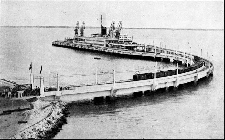
In the world of engineering the French have a well-deserved reputation for skill and ingenuity, particularly in harbour work and port development on a large scale. An outstanding example is provided by the work which has been accomplished in recent years by the engineers of the Port of Bordeaux. This work is remarkable, not only for its scope and size, but also for the ingenious methods which have been used. The jetty, or landing stage at Le Verdon, in the estuary of the River Gironde, is a fine piece of reinforced concrete work, a technique of which the French are complete masters. The landing stage has a total length of 1,236 feet, and the largest Atlantic liners can be berthed alongside it with ease. The landing stage is linked with the shore by a curved viaduct 1,258 feet long, which carries a railway and a road. Complete arrangements are provided on the landing stage for the disembarkation of passengers, who can proceed directly from the vessel to the boat train, thus avoiding the delay of having to wait on board while the ship sails up the river to Bordeaux, some sixty miles upstream. The mole is built on a number of huge concrete cylinders, which were filled with concrete after they had been sunk to the required level and upon a firm foundation. A special method, ingenious and simple, was used for sinking these cylinders. Numerous tubes were fixed to each cylinder, and within each tube was a smaller tube, down which compressed air was pumped. This air had the effect of forming an emulsion of air, water and mud at the bottom of the tube. Due to the air pressure, this emulsion rose in the tubes and was discharged from the cylinder above the water level. By means of a number of valves the amount of air entering the tubes was controlled, so that the progress of the tube could be accurately controlled. If it strayed from the vertical, then more air was admitted at the correct points and the cylinder was righted. Another interesting feature was the provision of water inlet valves, through which the entrance of water to the base of the tube could be controlled from above by a cable.
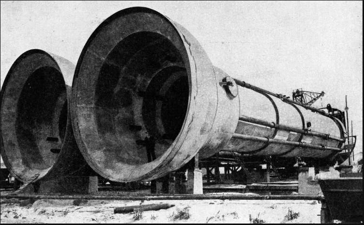
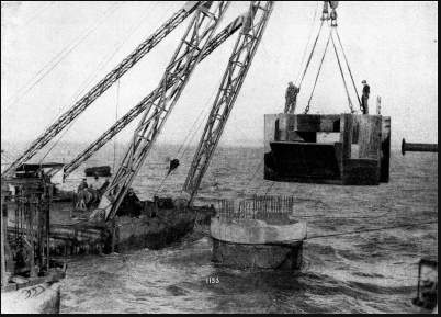
When a cylinder had been sunk to a firm foundation, the water inlets were shut, and the remaining water in the cylinder was pumped out. The cylinder was then filled with concrete, leaving a solid pillar as a foundation for the deck of the jetty. The engineers not only wished to take full advantage of the fact that there was a sandy bottom, but they also wished to avoid thfe use of large cranes, although one large crane was eventually procured. The first cylinders used were about 70 feet long. The engineers later used cylinders having a total length of 87 feet and weighing about 290 tons. It was decided, after long and careful thought, to build these huge cylinders on shore. The smaller cylinders, after one end had been plugged, were towed into position for sinking. The other end of each cylinder was provided with a platform, on which were placed all the control handles for the various valves. This served also as a working platform during the driving process. For the larger cylinders, a different method was adopted. The port authorities of Bordeaux bought a mammoth floating crane, capable of lifting a weight of 300 tons and provided with two hooks, each of which could handle a load of 225 tons and work independently of the other. By this means the cylinders were manoeuvred into position and sunk without difficulty. Equipped with a complete power plant and air compressors, the crane was thus used to control all operations on the site. After the cylinder had been launched the two hooks of the floating crane were attached ; one hook at about a third of the length from the top of the cylinder, the other near the bell-shaped base. Arrived at the correct position, the cylinder was then lowered into place by one of the crane hooks. During the sinking operation great care had to be exercised in keeping the cylinders vertical, as with tubes of such exceptional length it was extremely difficult to correct any considerable divergence from the vertical. The work was attended with many difficulties and obstructions in the form of buried beams of timber, or huge masses of rock and stone. When these obstructions stopped further progress, it was necessary to send a diver down to clear them away. Ingenious Shock AbsorbersThe rate of sinking averaged three feet an hour. The base of the cylinder was shaped in the form of a bell, the water being kept at bay by compressed air. The object of the bell-shaped base was to give a greater purchase to the cylinder rather than to allow men to work inside the bell. In the work at Bordeaux it was necessary to use this method in only one instance, when one of the cylinders got badly out of the vertical because of the bad ground. As soon as the cylinders had been sunk to a firm foundation, the building of the concrete superstructure was started. The cylinders were connected by light, shallow gangways, upon which ran small cranes. These were fitted with grab buckets, which deposited concrete into the cylinders, thereby converting them into solid and substantial piers. To make a good connexion between the tops of the cylinder piers and the superstructure, cleverly designed concrete caps were fitted to the tops; these caps served as moulds for the connecting beams. Each of the caps had to be made for the individual cylinder to which it was fitted, as the final level to which each cylinder was sunk varied considerably. Each cap weighed between 50 and 60 tons and was placed in position by the giant crane.
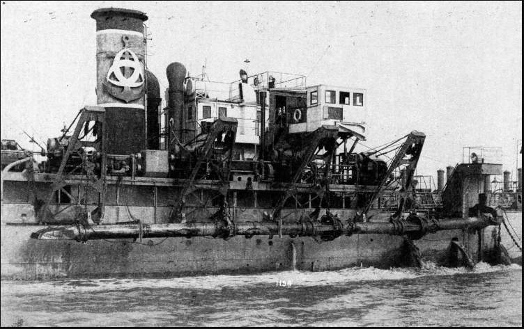
One of the most interesting problems connected with the jetty was to avoid the transmission of shock to the structure when a large vessel came alongside. Concrete is by no means a resilient substance. Under the action of an impact load it is apt to suffer serious damage. This damage may not be apparent at the time, but-large cracks may develop as time goes on, imperilling the safety of the whole structure. An ingenious shock absorber was, therefore, designed which could act as a buffer to a 60,000-tons liner approaching the jetty at a speed of 15 in. a second. The ordinary type of timber fender would be quite useless for absorbing the shock of a vessel such as the giant Normandie. The engineers of Bordeaux, therefore, set to work and designed a special form of hydraulic shock absorber. This mechanism is remarkable for its simplicity and effectiveness. It consists essentially of a large pendulum structure, pivoted at its upper end to the jetty on a large solid steel axle. A cylinder containing oil is built in below the underside of the jetty, and a closely fitting piston works inside it. When the vessel presses against the side of the pendulum, the oil is forced into an upper chamber through a pipe, thus effectively absorbing the shock. The pendulum itself weighs more than 30 tons, and in returning to its normal position under the force of gravity it pushes the vessel away from the jetty. Thus the piston moves forward in the cylinder, refilling it with oil and leaving the whole system ready to receive another shock. The engineers of the port were faced with an immense task of making a navigable channel from the sea through the estuary of the Gironde to Bordeaux. Remarkable Suction DredgerAfter a great deal of painstaking survey work, the engineers finally decided to dredge a channel, in an east-west direction, which would not tend to become silted. Heavy seas are encountered in the estuary and it was, therefore, necessary to design a special dredger for carrying out this work. Great credit is due to the engineers for having designed a vessel capable of work in rough seas. According to the reports of pilots, it was essential to have a dredger which could work for 200 days in the year in a sea in which the waves were 11-1/2 feet high. In such a seaway, dredging at anchor was clearly impossible and it was decided to build a special form of suction dredger. Known as the Pierre Lefort, this vessel is one of the largest ships of her type in the world. There are two suction tubes, one on either side of the vessel. These are lowered to the sea bed by tackles. The sand and mud are sucked up the tubes by the pumps in the hull of the dredger. Each suction tube slides down a guide in the ship's side. When a suction tube is lifted up on deck, the valves are closed, so that water cannot enter the hull. These valves are operated by special hydraulic gear. The sliding derricks, from which the suction tubes are suspended, are each provided with an electrically operated winch. The whole arrangement is simple and has proved to be effective in practice.
The greatest problem to be solved in designing this dredger was to provide efficient joints in the suction tubes, so that they would be able to bend with any movement of the vessel, and would also bp sufficiently robust. The type of joint finally adopted was a remarkable piece of mechanical ingenuity. It is a ball and socket joint and allows considerable movement, at the same time being strong. Some idea of its effectiveness may be gained from the fact that the Pierre Lefort has successfully continued her work in seas with waves more than 12 feet high. The seas continually broke over the bows of the vessel, about 18 feet above the water line. The dredger could have worked in even rougher seas. The limiting factor was the safety of the crew required to operate the valves and other machinery on deck. Another interesting feature of this vessel is the arrangement adopted for preventing the propeller shaft from being worn away by the sand. As dredging operations are continued, fine sand in suspension is continually being swept past the shaft during the passage of the ship through the water. This sand has a highly abrasive action on the shaft. The method of prevention consisted of circulating high-pressure water through a sleeve surrounding the propeller shaft. This pressure was amply sufficient to prevent the entrance of the sand. In addition, special steel propellers were fitted which were particularly resistant to sand erosion. When the bottom consists of sand or gravel, a dredging speed of about two knots is attained. In soft mud the speed can be raised to as much as three knots. When the dredger is working in soft mud, this substance is drawn up through the suction tubes in the form of a solid plug, having the consistency of a thick paste. The hold of the Pierre Lefort has a capacity of 2,600 cubic yards, and in these conditions could be completely filled in fifty minutes. Floating Power HouseThe vessel is a floating power house, for she is equipped with diesel engines, with a total power of 5,000 horsepower, driving electric generators. All the dredging operations, in addition to propulsion, are done by electric motors. These are controlled from a central switchboard on the bridge, which is provided with indicators giving the position of the submerged suction tubes and similar information. This complete electrical control gives a wonderful flexibility which would probably be impossible of attainment by any other means. Many people may be inclined to think that the huge suction tubes would make manoeuvring difficult. In practice, however, it has been found that the tubes act as stabilizers and restrict the rolling movement of the vessel considerably. By means of the electric winches and derricks the tubes are lifted easily and rapidly on deck after the dredging operations have been carried out. If dredging could always be carried out in calm water a single central suction tube would be the best arrangement. In a rough sea this is not practicable, for it has been found that the central tube is certain to be broken by the movement of the vessel and it has no stabilizing action. The electrical installation of the Pierre Lefort is of considerable size, and there are six separate groups of machinery. The twin screws are driven by two large electric motors of 1,150 horse-power, supplied with power from two generators. A generating set driven by diesel engines of 1,400 horse-power supplies power for the suction pumps. The remaining machinery consists of generators for supplying current to the auxiliary machinery all over the ship. Ample reserve power has been provided, so that the dredger can work even when some of the machinery is out of action.
Many thanks for your help
|
 |