|

|
Although there are many different types of boilers for generating steam at pressures which may range from 50 lb. to 1,000 lb. per sq. in., virtually all are made up of one or more steel drums or shells, generally with a number of fire tubes or water tubes. Thus the main methods of manufacture have much in common for all types. For steam pressures up to 250 lb., and when it is advantageous to have a boiler containing a large volume of water, one or other of the various kinds of "shell" or "tank" boiler is generally used. These include the Lancashire, with its two flue tubes ; the Cornish, with a single flue ; the "Economic" boiler, which contains also a number of fire tubes, generally placed above the flues ; and the Scotch marine type, which has a somewhat similar arrangement but is generally of much larger diameter than the "Economic" boiler. Then there are also a number of types of water tube boiler. Water tube boilers are generally adopted where steam pressures are relatively high; they are now used in all the more modern power stations at from 400 lb. to 650 lb. pressure. Certain special types have been made for pressures up to as much as 3,000 lb., in which event they are built almost entirely of tubes of small diameter. The differences in the methods of manufacture of these various types are mostly due to the steam pressures and temperatures at which the boilers have to work. The most common type, which might be taken as a fair example of. boilermaking, is the ordinary Lancashire boiler. The maximum size of this type made in standard form is about 9 feet in diameter and about 30 feet long. Lancashire boiler are built to stand working pressures up to 250 lb. First, a definite specification is drawn up by a responsible authority, and the essential requirements as to strength of materials, thickness of plates and tubes, and so forth, have to comply with standard regulations issued by the Board of Trade and by the insurance companies interested. The steel of which the plates and tubes are made has to pass stringent physical tests, such as those for tensile strength, shearing strength, elongation and the like. These tests are generally carried out at the steelworks, but most of the leading boiler manufacturers have their own laboratories where the tests can be made.
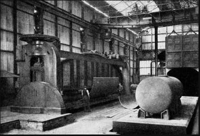
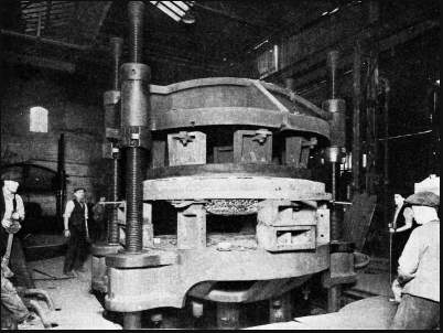
For example, the material for a Lancashire boiler of say 9 feet diameter, 30 feet long and for 150 lb. working pressure, would have to meet the following test conditions. The main shell plates would have to have a maximum tensile strength of from 28 tons to 32 tons per sq. in., with a minimum elongation of 20 per cent in a length of 8 in., thereby ensuring ductility. The plates for the ends and the flues would be slightly under this tensile strength, but with rather more elongation. The rivet steel must have 25 tons to 30 tons tensile strength, with an elongation of not less than 25 per cent in a length of 10 in. The factor of safety allowed in designing the dimensions of all parts under pressure is generally about five. That is to say, the strength of such parts is, as built, five times the strength required to stand the stresses to which they will be subjected in normal working conditions. When the steel plates, of required thickness and approximate size, are received in the boilerworks they are first put into a plate edge-planing machine, which planes the edges to the exact length and width. A few "tacking" holes are then drilled in the plates to hold them together during the main drilling operation. These tacking holes also enable the butt straps to be fitted directly the plates have been rolled to the required shape. The steel plate is then put into powerful vertical rolls, which bend it round to the desired circle. Such rolls deal with plates up to about in. thick. In some instances plates from 2-1/2 in. to 3-1/2 in. thick have to be bent to shape, and the operation is then carried out in a hydraulic press which does it in stages. Bending either by roll or by press is generally done with the plates cold, except with unusually thick plates. Ensuring a Perfect RivetWhen the main shell plates have been rolled they are placed in a drilling machine. If all the rivet holes were drilled in each section separately, and then bolted together for the riveting operation, it is possible that some of the holes would not come quite into line with the corresponding ones on the plate which had to be riveted to it. The plates are therefore held together by a few bolts in the tacking holes and the remaining rivet holes are then marked off. After this the shell plates, end plates and butt straps which cover the longitudinal seams are drilled at the one setting, so that every hole is true right through the two plates and a perfect rivet is assured. Before riveting, however, the assembled plates are taken adrift, so that any burrs or ragged edges left round the holes from the drilling operation can be dressed down, and any drill chippings which may have got between the plates may be removed. This precaution ensures perfectly clean surfaces so that when the plates have been riveted together they will close up. In Lancashire boilers the end plate may be flat, and secured to the shell by an angle-iron ring and stiffened by gusset plate stays, or, as is now more general, it may be a dished plate. This form of construction makes a cleaner job, and eliminates the gusset plate stays required for the flat end. Water tube boilers, which work at higher pressures, always have dished ends, although the drums are much smaller than those in the shell type of boiler. For the dished end, the plate is first cut roughly to size and then heated in a furnace to a suitable heat for heavy pressing. It is then placed in a powerful hydraulic press, capable of exerting a total pressure of about 600 tons. Cast-iron dies, to give the plate the desired shape, are fixed to the head and table of the press, one above the plate and the other below it. The dished form is generally completed in one pressing. There are, however, two flanged holes to be made in the plate, into which holes the two flues are fixed. These holes, varying in diameter from about 2 ft. 6 in. to 3 ft. 9 in., are then cut to a size which will, after having been pressed, be the correct size.
The end plate is then heated round the holes, and put into the press again to form the flanges which generally project outwards in the front end plate and inwards in the back end plate. An oval manhole opening near the bottom of the dished end, for access to the interior of the boiler, is also cut out and pressed in a similar manner. The dished end is then placed in a lathe, or in a vertical-spindle boring mill, to have the rough edges machined down to exact size and true, and the outer edge is turned. After this all ends are relieved of stress. Locating holes are drilled, and the dished end is bolted to the shell for the main drilling operation. The dished front end is then fitted into the front-end section plate, and the two or more circular sections, according to length of boiler, are then fixed together with locating bolts, but the back end plate is not yet put into position. The shell of the boiler is now ready for riveting. It is lifted on end by an overhead travelling crane in a tower, and the open bottom end is lowered over the standard, or arm, of the fixed riveting machine which carries the holding-on cup or snap for riveting. This machine is of great height as it must be capable of riveting up to the inner end of a long shell or drum. The circumferential rows are riveted by turning the shell round as required. The act of raising and lowering the shell, which is hanging freely on the crane, brings all intermediate holes in a vertical line into position for the operation. The seating blocks and pads to which valves and other fittings are fixed are also riveted at this stage. Water Pressure of 2,000 lb.Hydraulic riveters are much used in boilerworks, as great pressures are necessary to close the large sizes of rivets generally used. The pressure cylinder is generally made with two main rams of different diameters and a small auxiliary one. The size of rivets used is from 3/4 in. up to, say, 1-1/2 in., according to the thickness of plate, and a working pressure of from 50 tons to 70 tons is necessary to close the largest rivets. The water pressure used in the riveters, obtained by hydraulic pumps and an accumulator, is generally from 1,500 lb. to about 2,000 lb. per sq. in. During the riveting operation by a 100-tons riveter, the smaller of the two main rams is used first to press the plates together, with a pressure of, say, 30 tons. Then the larger ram closes the rivet, with a pressure of about 70 tons for a 1-1/4 in. rivet, and forms the head on it. Ultimately the whole weight of 100 tons is applied to the rivet head and plate. The auxiliary ram is used to move the main rams up to near the plate and to withdraw them after the operation has been completed, thereby avoiding the wasteful use of high-pressure water for the whole stroke. The small ram is supplied at low pressure from an overhead tank. The plate-closing operation prevents any "collar" from being formed on the shank of the rivet between the plates while in the hot state.
While these operations have been proceeding the flues have been going through their own process. The plates from which they are made are first planed in an edge-planing machine. They are then rolled approximately to the proper circle as they still have to be welded along the seam. This operation is generally done by a special water-gas welding machine, which does the work more quickly and satisfactorily than would be possible by hand. The flue section is secured by a tie strap clamped across the two sides of the seam edges of the plate, to prevent the plate from springing apart when under treatment. It is then placed horizontally on the floor carriage of the machine, with the seam uppermost. The machine consists of two long rigid cast-steel arms, at whose outer end are carried two cast-iron rollers so that the flue section can pass between them. The roller on the lower arm turns on a fixed axis, but that on the top arm is provided with a vertical movement and can have pressure applied to it by a hydraulic ram fixed to the end of that arm. For heating the part of the flue to be welded, a large rectangular burner, lined with firebrick, is suspended above the top side of the flue, and another is fixed inside the flue just facing the top burner. Water gas is fed to the burners and the amount of heat is controlled by the use of pyrometers. As soon as the proper welding heat has been reached the flue is moved so as to place the heated portion directly between the upper and lower rollers. While the heated portion is resting on the bottom roller the top roller is pressed down hard on to the weld by the hydraulic ram, and the flue is moved backwards and forwards along the weld, the rollers thus smoothing it out. The whole seam is thus completed in this progressive manner. The Flanging OperationThe flue section is now in a parallel cylindrical form, and still has to be flanged at the ends where riveted to an adjacent section. The flanging operation may be done in a vertical position by one form of flanger, or it may be carried out in what is virtually a simple chuck lathe. The end of the flue to be flanged having been previously heated to a suitable heat, the flue is quickly fixed in the chuck and made to rotate. At the other end of the machine is a roller fixed on an axis which can be rotated in the arc of a circle through about 90 degrees. The roller, at first in a horizontal position parallel to the axis of the flue, is made to press on the inside surface of the hot end, and is gradually moved round the arc until it is at right angles to the starting position. By the exertion of pressure on the roller the flue end is swaged over (shaped by pressure), at first taking a bell-mouth shape, finally to be bent over until it is at right angles to its axis. The other end having been treated in the same way if both ends are to be flanged, the flue is then placed in an annealing furnace to be treated, thereby neutralizing all the stresses which have been set up during the various processes through which it has passed. Sometimes one or more of the flue sections are made with circumferential corrugations of certain standardized forms. This not only increases the heating surface of the flue, but also strengthens it considerably, so that corrugated sections may be made longer than the plain ones and with fewer riveted joints. The corrugations also provide for expansion and contraction of the flues when fixed in the boiler and subjected to great ranges of temperature. The corrugated flues are at first made in the same way as parallel plain flues, so far as the welding of the seam is concerned. The flue is then again heated and placed in a special design of roller machine, whose rolls are made with the shape and size of corrugations required for the particular flue in hand. The top bearer frame of the roll is lifted off, the hot-flue is slipped over the operating-roller and the top housing is replaced in position. The flue is then rolled until it has taken on the full corrugations. It is then removed and flanged in a similar manner to the plain flue, after which it is placed in the annealing furnace.
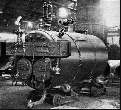
The flue flanges have now to be marked off, drilled for location bolts and then drilled right round. This can be done singly or in pairs. They are then separated again, all burrs removed, drill chippings cleaned out, and the two adjacent flanges bolted together for riveting. Because of the closeness of the rivets to the body of the flue it is necessary to use a riveter of special design for reaching awkward positions. Most of the riveting is done by portable hydraulic machines, but where flues are connected to the boiler end plates hand riveting is used. The whole length of sections of a flue is built up in this way, before it is inserted into the shell when that is ready. For a dished end Lancashire boiler the back and front ends of the flue are not flanged, these ends fitting into the parallel flanges of the holes in those plates and riveted to them. When the boiler is being assembled as a whole, the flue tubes are fixed in the back end plate of the boiler, which has not yet been riveted to the shell. The two flues, complete with end plate, are then fed into the shell. The end plate is finally bolted up ready for riveting and the riveting all round this end is done either by hand or with a pneumatic hammer. Caulking rings are fitted round the front end of each flue. The flue is then marked off and drilled with a portable drilling machine. Finally the two flues are riveted with a portable hydraulic machine to the front end plate. The back end flues are drilled in a similar manner, and then are riveted up, generally by hand. When such riveting is done by hand it is usual to bolt the joints here and there, especially close to the spot being riveted. These bolts are screwed up tightly to maintain close metallic contact between the plates while the work proceeds, after which the bolts are removed, one by one, as their place is about to be taken by rivets. When the whole of the riveting has been completed, all the plate edges are gone over carefully with a caulking tool, to make sure that all the joints will be steam-tight. The caulking tool is similar to a blunt cold chisel and is applied by hammer blows. Hydraulic TestThe boiler is now ready for its hydraulic test. Blank flanges are fitted to all outlet connexions, and the boiler is filled up with water. Then the necessary test pressure is applied. In the boilermaker's works this is generally done by connecting the boiler to high-pressure hydraulic mains. If, as is general, this pressure is much higher than that at which the boiler is to be tested, a reducing valve is used to bring the pressure down to whatever is required. For hydraulic tests of a boiler after delivery on site, or where no such high-pressure water mains are available, the necessary pressure is applied by a small test pump after the boiler has been filled up with water. The usual water test pressure for steam boilers is 50 lb. more than one and a half times the working pressure. If the working pressure is to be 150 lb. per sq. in., the hydraulic test pressure would be 150 plus 75 plus 50, or a total of 275 lb. per sq. in. Although every boiler made has to pass specified tests by the insurance companies engaged in the interests of the buyer, boilermakers often carry out such tests for their own satisfaction. After the boiler has been delivered on site, it is usual, or at any rate advisable, especially if it has travelled a long distance and may have suffered some strain, to repeat the hydraulic test after the boiler has been placed on its foundation bed. Full steam tests are generally carried out on site when the whole installation has been completely erected. The manufacture of other boilers classed more or less in the "shell" type, such as Cornish, Scotch marine, or " Economic " boilers, is carried out on similar lines. In the water tube types, however, the boiler proper is even simpler, and generally has to stand more severe working conditions.
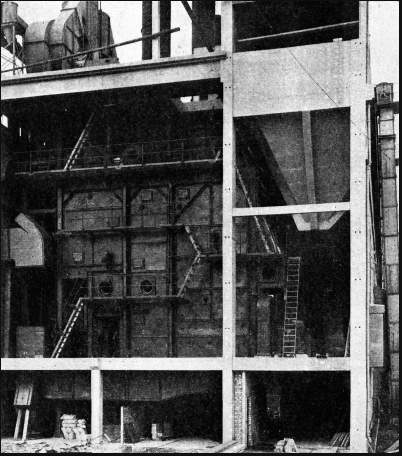
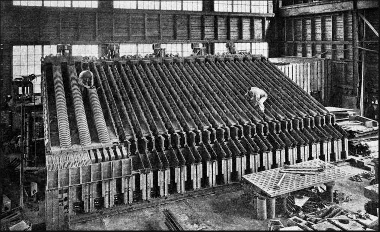
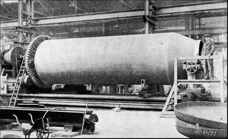
In this instance the steam and water drums may be made in much the same way as the shell of the Lancashire boiler, but, being of much smaller diameter, they can sometimes be made in one long single drum. This may be electric fusion welded along the longitudinal and circumferential seams. The electric fusion welding of high-pressure boiler drums has reached such an advanced stage that it is now possible to see right into the weld by X-ray apparatus specially designed for the purpose. When the ends are made separately from the drums, they are always of the dished type, and are carefully machined round the outer periphery. The corresponding part of the inside of the drum end is also machined, so that the two surfaces fit exactly all round, before being riveted up. The drums have then to be drilled for the hundreds of water tubes which have to be fitted to them. The tube holes receive a final boring with a tool which gives a finely machined finish to the surface. This is of utmost importance when the tubes are being expanded into the drum, as it secures a satisfactory steamtight metal-to-metal joint between the two surfaces. Some types of water tube boilers use only straight tubes, some have more or less bent ones, and others use a combination of both. The advantages of tubes bent at the ends are that this construction enables the tubes to enter the shell of the relatively small drum as nearly as possible at a right angle, thus securing a uniformly shaped hole. So long as a straight tube is led from near the centre of one drum to a corresponding position in the drum at the other end, the holes will be square to the drum ; but as they get farther round the periphery of the drum they enter it at an increasingly acute angle, making it more difficult to obtain a good joint. Another advantage claimed for the bent tube is that it allows more flexibility for expansion due to changes of temperature. Powerful Wedge ActionThe bending is performed in a cold state in a power-operated tube-bending machine, which does the work without flattening the form of the tube at the bend. One well-known type of boiler using straight tubes is of somewhat different construction, the tubes not being expanded into the drums. To either end of the steam drums is connected a series of inclined vertical corrugated headers, into which the tube ends are expanded. Caps in the headers opposite the tube ends provide access for cleaning and inspection. The tubes for water tube boilers are made from the best mild steel, having to stand, on the fire side, high temperatures. In many instances the tubes are subjected to 1,000-lb. hydraulic test, according to the working pressure of the boiler. It is of considerable advantage to have the fewest possible different shapes of bend in the tubes of any one boiler, so that the number of spare tubes to be kept can be a minimum. The expanding of the tubes is done by a special tool comprising three or more hard steel rollers mounted on a central mandrel. These are made with a slight taper, so that, as the tool is pressed into the tube end and rotated, it has a powerful wedge action in expanding the tube end against the sides of the hole in the drum. For large tubes, or when many tubes are to be treated, the expanding tool may be driven by a small compressed-air motor. The extent to which the water tube boiler is completely erected in the maker's works will depend on its size. It may be partly assembled at the works, but much of the assembly of the larger boilers has to be left until finally delivered on site. In the modern large power station installation there are so many accessories such as economizers, or water heaters, steam superheaters, air heaters, forced-draught or induced-draught equipment and so on, that in a drawing of the layout of such a plant, the boiler appears to be only a small part of it, though it does most of the work.
Many thanks for your help
|
 |