| The MS-1 Small Escort Tank |
|---|
|
|
The hull of the tank is of riveted construction, from armored plates of 8-16 mm thickness assembled on a frame. The early production tanks had special two-layered (base and top) and three-layered armor plates produced using the method of A. Rozhkov. Later, in order to economize on production costs of the tank, conventional one-layered armor was employed. The tank was divided into three compartments: |
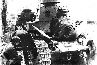
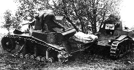
The driver's compartment was at the front of the tank. A tri-fold hatch provided the driver-mechanic access to the compartment. Two of its panels folded back to the left and right. Movement of these panels was limited by latching mechanisms. The front folding shield raised upward and was held in this position by a lock. In the right portion of the shield was a lug for mounting the body of a monocular observation periscope (armored glass). On the left side of the shield was a narrow vision slit. In the event of intensive enemy fire, it could be covered by an armored shutter with two cross-shaped apertures. When absolutely necessary the vision slit could be completely covered. Similar narrow vision slits covered by internal sliding shutters mounted in the forward slopes provided a panoramic field of view of the battlefield. Brackets were mounted to the sides of the bow portion of the hull under the idler wheel axle. The purpose of these brackets was to regulate the tension of the tracks with the aid of special anchors located on the sides of the tank. On front left track tension mechanism bracket was a headlight and on the right side a horn. In a combat situation the light folded into the hull of the tank. The rear light was covered with a red glass lens and mounted on the left side of the hull (sometimes on the right above the exhaust pipe). It served not only as a warning device in darkness but also as a light device for guiding a column. A peculiarity of the construction of the hull was that it was built without any under-turret box. However, on the upper sides of the hull were attached special triangular-shaped "boxes" (the spaces above the tracks), which contained the fuel cells. The filler spouts for these fuel cells were covered by armored caps. For access to the fuel cell, in the rear portion of the "box" was a cover secured by three bolts and in addition a securing ring. Upon removal of the bolts the cover opened to the side on a hinge. These "boxes" hanging over the tracks also served the function of fenders in the middle of the vehicle. On the rear of the tank were fenders made from thin metal, and on the front of the tank fenders made from canvas (a small number of tanks produced in the first series had metal or plywood fenders on the front). A shaped piece of armor plate, which when necessary can be folded downward on pivot pins to provide access to the engine compartment, covers the engine-transmission compartment of the tank. On top of the engine compartment cover, which can be folded upward and forward, is mounted a cowl with a slotted opening oriented toward the turret. Its purpose is to permit cooling air into the engine and simultaneously protects the engine compartment against penetration by enemy fire. The rear portion of the hull has a shaped recess, which on the backside is covered by a metal casing with a row of small-diameter holes. Heated air from the engine compartment is directed toward these holes by a directional flue and is released outside the tank. This flue can be closed by a door to retain the heated air for engine warming. A vertical armor plate positioned in front of the metal casing from the motor protects the motor against damage from projectiles and shrapnel. |
Inside the hull the fighting compartment is isolated from the engine compartment by a partition. This partition has a bi-folding door with lock for accessing the engine compartment from inside the tank. On the partition also are mounted taps for shutting off the flow of fuel from the right and left tanks and a tap for regulating the fuel flow to the engine by pressure pump or gravity. In the bottom of the hull under the fighting compartment is a hatch that permits the discard of expended shell casings and the removal of water that has fallen into the hull. The hatch is closed with a cover and is held by a lever that is secured by a hand-tightened release. For ease of work in the tank the top of this hatch cover is covered by a platform insert (to bring the hatch up to floor level). On tanks of initial production there is also a hatch in the hull bottom under the engine area, however it provided small benefit and based on instructions from the OAT (Ordnance-Arsenal Trust - a central design directorate for weapons and combat equipment) dated 14 February 1930, this hatch was deleted from the design. To the rear portion of the hull was attached an extension-a "tail", which permitted the relatively short tank to overcome broad trenchworks. Two attachment loops were welded to the lower portion of the rear hull and one loop on the front hull for evacuation of the tank should it become disabled or mired. |
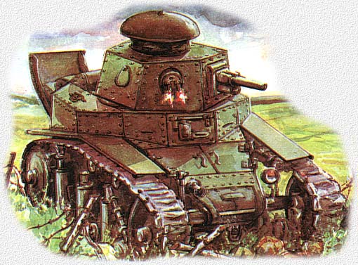
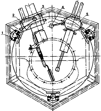
The tank's turret was riveted, and initially had an almost rectilinear six-sided shape with inclined walls. It rested on the sub-turret armor plate through a bearing race and rotated by means of a manual crank. On the back wall of the turret was a backrest, on which was hung a broad strap that the commander used for a seat. The turret was held at the desired position of rotation by three stops spaced equally on the turret ring, two in front and one at the rear. On the roof of the turret was an observation cupola with hatch cover that opened on hinges. Springs were contained in the hinge that helped to open the hatch and a latch was installed to hold it in the open position. Ventilation holes were formed around the perimeter of the hatch base that could be covered when necessary with a sliding circular shield. Observation slits in the vertical walls of the cupola were provided with leather facings to protect the commander's face against bruising, and the cupola itself had a ventilator hole covered by a sliding shield of a teardrop shape where the cupola was joined with the turret roof. The shape of the turret was changed when the tank was modernized. Additional space was added at the rear of the turret for the installation of a radio set. The recess was closed from the back by a folding cover that permitted installation and removal of the radio and weapon (actually, a portion of the ammunition stowage was in this space). The shield for the ventilating portal of the turret became rectangular and now folded upward on hinges. The new turret was 140 kg heavier. The tank's armament, consisting of a 37mm Hotchkiss cannon and machine gun, was located in the forward portion of the turret. The cannon was located on the left side in a rectangular opening and the machine gun on the right side in a ball mounting. When necessary the machine gun could be shifted to a hull opening that was located on the left rear face and covered in normal conditions by an armor plate. |

| 1. Turret brake; 2. Handle for rotating turret; 3. Vision slit; 4. Cupola hatch cover; 5. Cupola hatch cover handle; 6. Turret race mount; 7. Upper turret ring; 8. Lower turret ring. |
Initially the artillery armament of the tank consisted of a 37mm Hotchkiss cannon. The weapon's barrel, with a length of 20 calibers, was borrowed from a naval cannon of the same name, but the wedge-type breech had a different design. The recoil mechanism consisted of a hydraulic compressor-brake and recoil spring, assembled together. Officially the cannon was accepted for armament in the Red Army in 1920 and mounted on the "Russian Renault" tank and several armored cars. The cannon was mounted on the first series of T-18 tanks from old stocks, among which were models that had "reverse" threads (counterclockwise). However in 1928 it was replaced by the 37 mm PS-1 Cannon, made in Soviet Russia and presented as a variant of the Hotchkiss modernized by Peter Syachintov. The striker and firing mechanism in the PS-1 were changed, along with the cannon cover. The Soviet-produced version was simpler in production and included a recoil moderator, an equalizer for easing vertical lay, change in shell holder, shoulder rest, and so on. Single-loading shells which were stored in canvas bags inside the tank were used in the cannon. On tanks of the initial production series, the guns were equipped only with diopter sights. However, in 1929 the Motovilikha Machine-building Plant began the assembly of the 2.45-power optical sight for the 37 mm Tank Cannon with a field of view of 14°20' and an exit pupil diameter of 2.6 mm. This sight, developed in Leningrad, was mounted on some T-18 tanks produced after 1930. The modernization of the tank in 1929-30 was undertaken to increase its firepower by mounting the more powerful 37 mm B-3 Cannon, produced in accordance with re-worked features by the Rhinemetall firm. This new gun differed in that it had greater firing range and also a semi-automatic breech mechanism. A tank equipped with this new cannon had a significant advantage in armament. Simultaneous with the mounting of a new gun, which had greater weight than the old gun, the decision was made to balance the turret, which led to the appearance of a new rear stowage compartment. However, the production of the B-3 cannon was not fully underway practically until 1932, and the first tank that received these cannons was the BT-2. The T-18 continued to be equipped with the PS-1. The machine gun armament of the tank consisted initially of the two-barreled 6.5-mm Fedorov-Ivanov tank machinegun in a Shpagin ball mounting. However the life of this machine gun was very short. In 1930 the Degtyarev Tank Machinegun (DT), which was the basic automatic weapon of Soviet tanks for the next 25 years, was adopted for the arming of all tanks in the Red Army. |
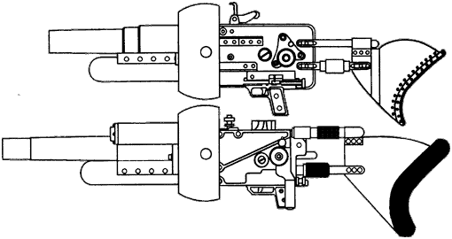
| 1. Turret brake; 2. Horizontal gun armor shield; 3. Vertical gun armor shield; 4. Machine gun ball mount lock handle; 5. Ball shield. |
The mobility of this tank was provided by a gasoline four-cylinder, four-stroke, air-cooled engine designed by A. Mikulin, producing 35-40 h.p. In comparison with existing power plants of tanks of that era, it had some peculiarities. For example, ignition was provided by two sets of spark plugs (two spark plugs per cylinder) from a magneto, which ensured that a powerful spark was distributed to each cylinder when the motor was started, and from a dynamo-magneto, which served both for ignition and for supplying the driving lights. The second peculiarity was the unified engine and transmission in a single assembly and the clutch (primarily friction), which was an absolute innovation at that time. And finally, the engine was mounted transversely in the engine compartment, which gave the tank a measurable superiority in weight and length compared to tanks that had a longitudinally mounted power pack. The simple differential was joined to the transmission, on the output shafts of which were mounted gears. Together with drive wheels they comprised the tank's final drive. On tanks of the third series, the output of the engine was increased to 40 h.p., which together with a four-speed transmission enabled the tank to reach a speed of 17.5 kmh. The first production series of tanks were equipped with Bosch electrical systems and tanks produced after 1930 were equipped with Sintilla electrical systems. |

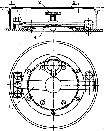
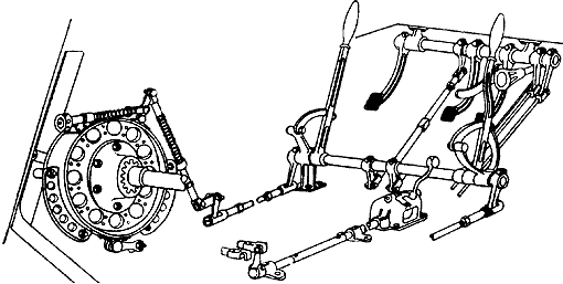
The drive wheel consisted of an aluminum hub with steel rim attached with external and internal teeth. On the outside this wheel was covered by an armored shield. The hub rested on the axle over two bearing races. The idler was an aluminum disk with a spacer ring and two rubber linings. The idler arm, by which the idler wheel was attached to a bracket on the hull, was elbow-shaped, and rotated in the hull bracket, supporting the track under tension. The suspension and running gear of the tank consisted of six bogies with shock absorbers and a pair of rollers. In addition, the first pairs of rollers were joined with an additional support roller by a linking mechanism (see illustration). On early production tanks the design of the forward suspension bracket differed from the two rear brackets by the presence of eyes for attachment of the linking mechanism to the front supporting roller. Its springing lengthened the moment arm of the suspension mechanism. Beginning in 1930, standardized brackets were mounted. The upper run of the track lay on four rubber-lined support rollers (on each side). The first three rollers were held up by leaf springs. All the rubber linings of the tank's running gear were manufactured at the plant "Krasnij Treugolnik" (The Red Triangle). The track of the T-18 consisted of 51 blocks (actually from 49-53). The track blocks of early production were complicated in manufacture. The consisted of a cast base with ears and a ridge for engagement with the drive sprocket. To the outer portion of the block was riveted a steel flange with lateral lap joints for increasing the magnitude of the bearing surface during the tank's movement on soft ground. The top of the flange had a grouser riveted to it to improve traction. The track blocks were connected to each other by a hollow steel bolt. These bolts were contained on both ends by bronze bushings attached with cotter pins. Beginning in the summer of 1930, tanks began to receive new track made from cast track blocks of the "eagle claw" type, which were highly effective, especially in soft soil. |

Band brakes were intended for use in turning the tank. They also were employed for stopping the tank to fire and for parking brakes. The brake drum for the left or right track was located on the differential shaft between the differential case and the final drive sprocket. Two levers and a pedal were provided to control these brakes. Both levers or the brake pedal could be used to stop the tank. A toothed sector that held the brake pedal in the depressed position was used for a parking brake. The gear linkage with lever was mounted under the driver-mechanic's right hand on the floor. The handle for controlling the ignition (linkage to the magneto) was located on the driver's left side. Gauges were mounted on a plate to the right of the driver-mechanic on the side of the tank. In addition to instruments, on this plate were mounted the central switch for distribution of current between components (running lights, starter, horn), gauges to monitor oil pressure and temperature in the system and the engine, magneto switch, starter button, inspection and illumination lamps, and horn button. The storage battery was to the right of this plate on the vehicle floor. The light switch was mounted on the lower front slope of the hull. The tank had no special instruments for internal or external communication. True, in 1929 the OAT issued a tasking to the Scientific Test Institute of Communications for a tank radio set. In particular the institute was instructed in writing to prepare not one, but immediately three radio sets, one each for the ordinary tank, platoon commander, and company commander. These radio sets were created, but not one of them was normally inserted into the space reserved for them because the mounting bolts, brackets, and hardware were not taken into consideration during the issuing of the manufacturing order. |

| REFERENCES: T-18 Development History Combat Employment of the T-18 Production vehicles based on T-18 Specification of the Soviet tank guns Specification of Soviet tanks |
Translated by:
James F. Gebhardt Sources: "First Soviet Tanks", Armada #1, M. Svirin and A. Beskurnikov "First Serially Produced Small Escort Tank MS-1", Arsenal-Press, A. Beskurnikov, Moscow 1992 |